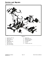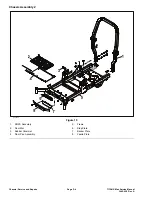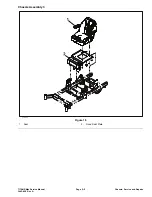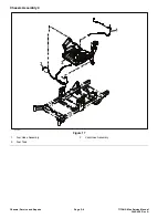
Right Console Removal (continued)
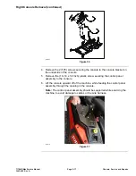
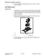
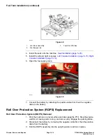
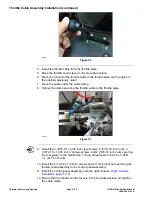
g343007
Figure 36
4. Remove the 2 (T25) screws securing the console to the console bracket on
the underside of the console.
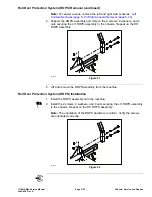
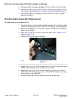
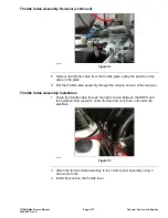
5. Remove the (10–14 x 1/2 inch) plastic screw securing the control panel
assembly to the console.
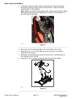
6. Lift the console upward off of the machine, while feeding the control panel
assembly through the opening in the console.
Note:
The control panel assembly should be supported while servicing the
machine, to avoid damage to cables or the wire harness.
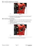
g344218
Figure 37
TITAN® Max Service Manual
Page 5–17
Chassis: Service and Repairs
3442-428 Rev A
Содержание TITAN
Страница 2: ...Revision History Revision History Page 2 TITAN Max Service Manual 3442 428 Rev A ...
Страница 6: ...Preface Page 6 TITAN Max Service Manual 3442 428 Rev A ...
Страница 20: ...Specifications and Maintenance Torque Specifications Page 2 10 TITAN Max Service Manual 3442 428 Rev A ...
Страница 26: ...Troubleshooting General Troubleshooting Page 3 6 TITAN Max Service Manual 3442 428 Rev A ...
Страница 36: ...Engine Service and Repairs Page 4 10 TITAN Max Service Manual 3442 428 Rev A ...
Страница 70: ...Chassis Service and Repairs Page 5 34 TITAN Max Service Manual 3442 428 Rev A ...
Страница 92: ...Mower Deck Service and Repairs Page 6 22 TITAN Max Service Manual 3442 428 Rev A ...
Страница 118: ...Electrical System Service and Repairs Page 8 18 TITAN Max Service Manual 3442 428 Rev A ...
Страница 121: ... Drawing Rev A Sheet 1 3442 428 Rev A Page A 3 Kohler Engine Electrical Schematic g350654 ...

