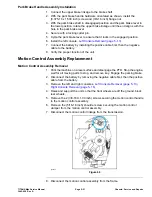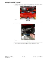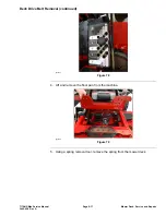
Motion Control Assembly Removal (continued)
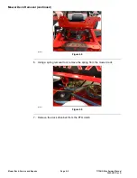
g336044
Figure 61
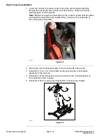
9. Lower the motion control assembly through the frame toward the center of
the machine, remove the assembly.
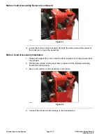
Motion Control Assembly Installation
1. Raise and support the unit so that the front wheels are off the ground, block
rear wheels.
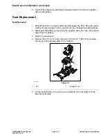
2. Position the motion control assembly in place with the linkage extending
toward the transmission.
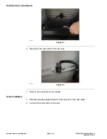
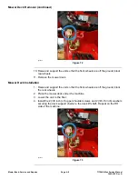
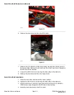
3. Secure the motion control assembly to the frame.
g336044
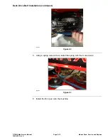
Figure 62
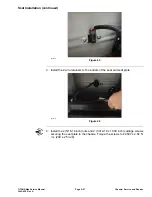
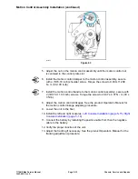
4. Connect the motion control linkage to the transmission.
Chassis: Service and Repairs
Page 5–32
TITAN® Max Service Manual
3442-428 Rev A
Содержание TITAN
Страница 2: ...Revision History Revision History Page 2 TITAN Max Service Manual 3442 428 Rev A ...
Страница 6: ...Preface Page 6 TITAN Max Service Manual 3442 428 Rev A ...
Страница 20: ...Specifications and Maintenance Torque Specifications Page 2 10 TITAN Max Service Manual 3442 428 Rev A ...
Страница 26: ...Troubleshooting General Troubleshooting Page 3 6 TITAN Max Service Manual 3442 428 Rev A ...
Страница 36: ...Engine Service and Repairs Page 4 10 TITAN Max Service Manual 3442 428 Rev A ...
Страница 70: ...Chassis Service and Repairs Page 5 34 TITAN Max Service Manual 3442 428 Rev A ...
Страница 92: ...Mower Deck Service and Repairs Page 6 22 TITAN Max Service Manual 3442 428 Rev A ...
Страница 118: ...Electrical System Service and Repairs Page 8 18 TITAN Max Service Manual 3442 428 Rev A ...
Страница 121: ... Drawing Rev A Sheet 1 3442 428 Rev A Page A 3 Kohler Engine Electrical Schematic g350654 ...

