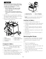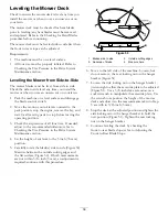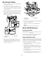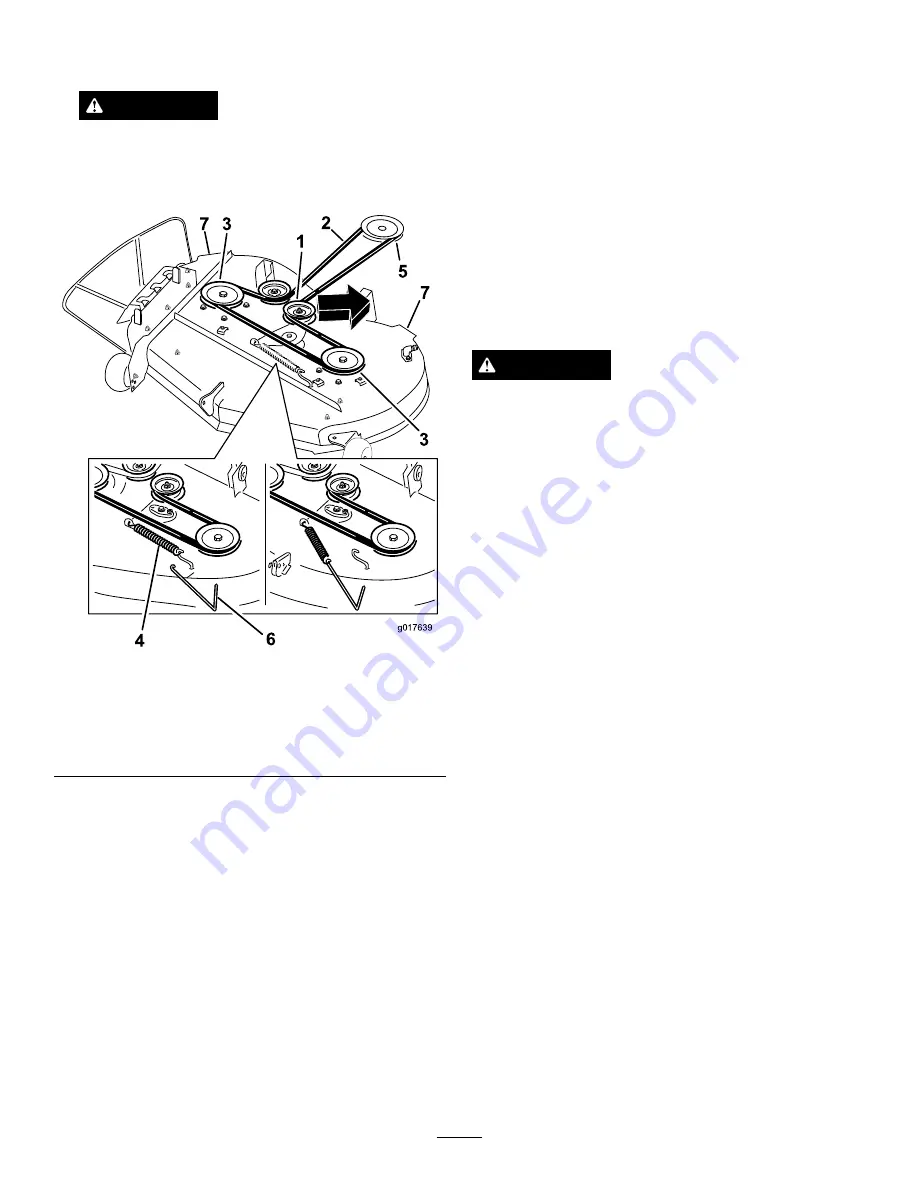
remove tension on the idler pulley and roll the belt
off of the pulleys (Figure 56).
WARNING
The spring is under tension when installed and
can cause personal injury.
Be careful when removing the belt.
g017639
1
2
3
3
5
4
6
7
7
Figure 56
1.
Idler pulley
5.
Engine pulley
2.
Mower belt
6.
Spring removal too
3.
Outside pulley
7.
Mower deck handles
4.
Spring
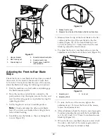
5. Route the new belt around the engine pulley and
mower pulleys (Figure 56).
6. Using a spring removal tool, (Toro part no. 92-5771),
install the idler spring over the deck hook and
placing tension on the idler pulley and mower belt
((Figure 56).
Installing the Mower
1. Park the machine on a level surface and disengage
the blade control switch.
2. Move the motion control levers outward to the
park position, stop the engine, remove the key, and
wait for all moving parts to stop before leaving the
operating position.
3. Slide the mower under the machine.
4. Lower the height-of-cut lever to the lowest position.
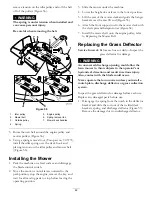
5. Lift the rear of the mower deck and guide the hanger
brackets over the rear lift rod (Figure 55).
6. Attach the front support rod to the mower deck with
the clevis pin and hairpin cotter (Figure 54).
7. Install the mower belt onto the engine pulley; refer
to Replacing the Mower Belt.
Replacing the Grass Deflector
Service Interval:
Before each use or daily—Inspect the
grass deflector for damage
WARNING
An uncovered discharge opening could allow the
lawn mower to throw objects in the operator’s or
bystander’s direction and result in serious injury.
Also, contact with the blade could occur.
Never operate the lawn mower unless you install a
mulch plate, discharge deflector, or grass collection
system.
Inspect the grass deflector for damage before each use.
Replace any damaged parts before use.
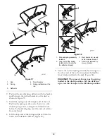
1. Disengage the spring from the notch in the deflector
bracket and slide the rod out of the welded deck
brackets, spring, and discharge deflector (Figure 57).
Remove the damaged or worn discharge deflector.
42
Содержание TimeCutter MX 4260
Страница 10: ...119 8874 1 Low speed 2 High speed 10 ...
Страница 11: ...121 0772 1 Fast 4 Choke 2 Continuous variable setting 5 Power take off PTO Blade control switch 3 Slow 11 ...
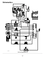
Страница 48: ...Schematics g017655 Electrical Diagram Rev A 48 ...
Страница 49: ...Notes 49 ...
Страница 50: ...Notes 50 ...
Страница 51: ...Notes 51 ...

