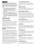
WARNING
Incorrect battery cable routing could damage
the machine and cables causing sparks. Sparks
can cause the battery gasses to explode,
resulting in personal injury.
•
Always disconnect the negative (black)
battery cable before disconnecting the
positive (red) cable.
•
Always connect the positive (red) battery
cable before connecting the negative (black)
cable.
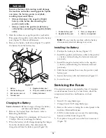
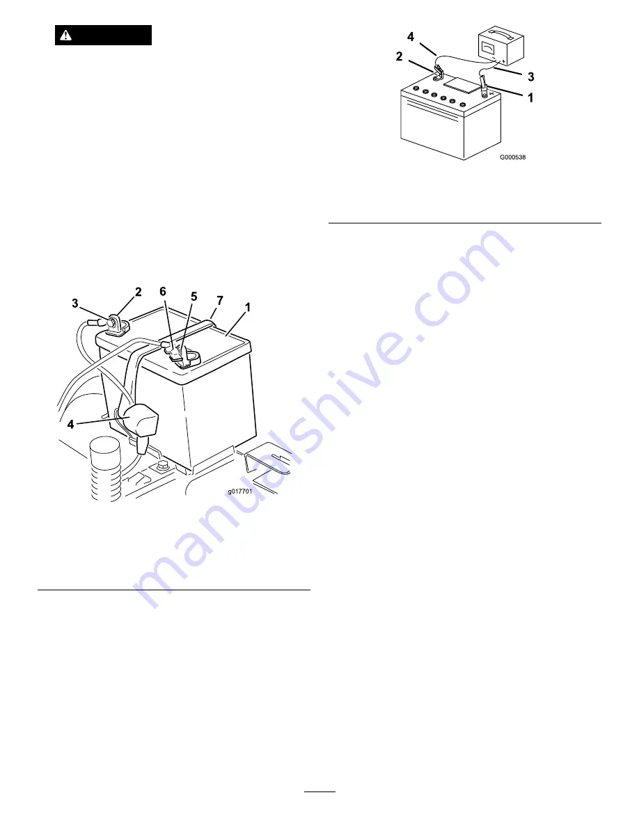
5. Slide the rubber cover up the positive (red) cable.
Disconnect the positive (red) cable from the battery
post (Figure 37). Retain all fasteners.
6. Remove the battery hold-down (Figure 37) and lift
the battery from the battery tray.
g017701
2
3
4
5
6
7
1
Figure 37
1.
Battery
5.
Negative battery post
2.
Positive battery post
6.
Wing nut, washer, and bolt
3.
Bolt, washer, and nut
7.
Battery hold-down
4.
Terminal boot
Charging the Battery
Service Interval:
Before storage—Charge the battery
and disconnect battery cables.
1. Remove the battery from the chassis; refer to
Removing the Battery.
2. Charge the battery for a minimum of 1 hour at 6 to
10 amps. Do not overcharge the battery.
3. When the battery is fully charged, unplug the charger
from the electrical outlet, then disconnect the
charger leads from the battery posts (Figure 38).
Figure 38
1.
Positive battery post
3.
Red (+) charger lead
2.
Negative battery post
4.
Black (-) charger lead
Note:
Do not run the machine with the battery
disconnected, electrical damage may occur.
Installing the Battery
1. Position the battery in the tray (Figure 37).
2. Install the positive (red) battery cable to the positive
(+) battery terminal using the fasteners removed
previously.
3. Install the negative battery cable to the negative
(-) battery terminal using the fasteners removed
previously.
4. Slide the red terminal boot onto the positive (red)
battery post.
5. Secure the battery with the hold-down (Figure 37).
6. Lower the seat.
Servicing the Fuses
The electrical system is protected by fuses. It requires
no maintenance; however, if a fuse blows, check the
component/circuit for a malfunction or short.
Fuse:
•
Main F1-30 amp, blade-type
•
Charge Circuit F2-25 amp, blade-type
1. Remove the screws securing the control panel to the
machine. Retain all fasteners
2. Lift the control pane up to access the main wiring
harness and fuse block (Figure 39).
3. To replace a fuse, pull out on the fuse to remove it
(Figure 39).
34
Содержание TimeCutter MX 4260
Страница 10: ...119 8874 1 Low speed 2 High speed 10 ...
Страница 11: ...121 0772 1 Fast 4 Choke 2 Continuous variable setting 5 Power take off PTO Blade control switch 3 Slow 11 ...
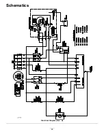
Страница 48: ...Schematics g017655 Electrical Diagram Rev A 48 ...
Страница 49: ...Notes 49 ...
Страница 50: ...Notes 50 ...
Страница 51: ...Notes 51 ...

