


Reelmaster 7000
Page 5 -- 27
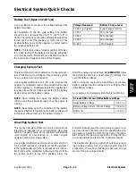
Electrical System
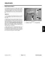
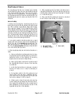
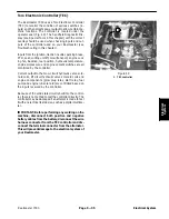
Mow/Transport Sensor
The mow/transport sensor is a normally open proximity
sensor that closes when the mow speed limiter is placed
in the transport (2WD) position. The sensor mounts to
a bracket on the footrest platform. The sensing plate for
the mow/transport sensor is the mow speed limiter. The
mow/transport sensor is used as an input for the TEC
controller.
Sensor Testing
1. Before disconnecting the mow/transport sensor for
testing, the sensor and its circuit wiring should be tested
as a TEC controller input with the Diagnostic Display
(see Diagnostic Display in the Troubleshooting section
of this chapter). If the Diagnostic Display verifies that the
mow/transport sensor and circuit wiring
are
functioning
correctly, no further sensor testing is necessary. If, how-
ever, the Diagnostic Display determines that the mow/
transport sensor and circuit wiring
are not
functioning
correctly, proceed with testing procedure.
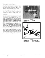
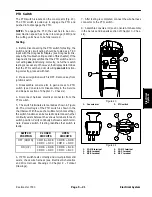
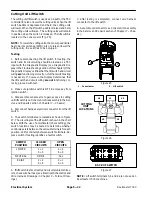
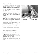
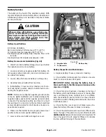
2. Turn ignition switch to the ON position (do not start
engine) and check LED on cable end of mow/transport
sensor (Fig. 35). LED
should be
illuminated when the
mow speed limiter is in the TRANSPORT (2WD) posi-
tion. The LED
should not be
illuminated when the limit-
er is in the MOW (4WD) position.
3. If the mow/transport sensor LED did not function cor-
rectly:
A. Make sure that the mow/transport sensor is prop-
erly adjusted (see Mow/Transport Sensor in the Ad-
justments section of this chapter). If necessary,
adjust sensor and return to step 2 above.
B. Make sure ignition switch is OFF and disconnect
the mow/transport sensor connector from machine
wire harness.
C. Verify that the machine wire harness connector
terminal for black wire is closed (continuity) to
ground.
D. Turn ignition switch to the ON position (do not
start engine) and verify with a multimeter that ma-
chine wire harness connector terminal for pink wire
has system voltage (12 VDC) present.
E. If black wire is closed to ground, pink wire has
system voltage present and sensor LED did not func-
tion, replace mow/transport sensor. Adjust sensor
after installation (see Mow/Transport Sensor in the
Adjustments section of this chapter).
4. If the mow/transport sensor tests correctly and a cir-
cuit problem still exists, check wire harness (see Electri-
cal Schematic and Wire Harness Drawings in Chapter
9 -- Foldout Drawings).
5. Make sure that mow/transport sensor is connected
to wire harness when testing is complete.
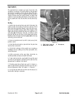
1. Mow speed limiter
2. Mow/transport sensor
3. Sensor cable
Figure 35
1
2
3
Electrical System
Содержание Reelmaster 7000
Страница 2: ...Reelmaster 7000 This page is intentionally blank ...
Страница 4: ...Reelmaster 7000 This page is intentionally blank ...
Страница 10: ...Reelmaster 7000 Page 1 6 Safety This page is intentionally blank ...
Страница 12: ...0 09375 Reelmaster 7000 Page 2 2 Product Records and Maintenance Equivalents and Conversions ...
Страница 34: ...Reelmaster 7000 Page 3 18 Kubota Diesel Engine This page is intentionally blank ...
Страница 36: ...Reelmaster 7000 Hydraulic System Page 4 2 This page is intentionally blank ...
Страница 45: ...Reelmaster 7000 Hydraulic System Page 4 11 This page is intentionally blank Hydraulic System ...
Страница 115: ...Reelmaster 7000 Hydraulic System Page 4 81 This page is intentionally blank Hydraulic System ...
Страница 131: ...Reelmaster 7000 Hydraulic System Page 4 97 This page is intentionally blank Hydraulic System ...
Страница 139: ...Reelmaster 7000 Hydraulic System Page 4 105 This page is intentionally blank Hydraulic System ...
Страница 147: ...Reelmaster 7000 Hydraulic System Page 4 113 This page is intentionally blank Hydraulic System ...
Страница 151: ...Reelmaster 7000 Hydraulic System Page 4 117 This page is intentionally blank Hydraulic System ...
Страница 168: ...Reelmaster 7000 Hydraulic System Page 4 134 This page is intentionally blank ...
Страница 214: ...Reelmaster 7000 Page 5 46 Electrical System This page is intentionally blank ...
Страница 221: ...Reelmaster 7000 Page 6 7 Axles Planetaries and Brakes This page is intentionally blank Axles Planetaries and Brakes ...
Страница 227: ...Reelmaster 7000 Page 6 13 Axles Planetaries and Brakes This page is intentionally blank Axles Planetaries and Brakes ...
Страница 247: ...Reelmaster 7000 Page 7 3 Chassis This page is intentionally blank Chassis ...
Страница 264: ...Reelmaster 7000 Page 7 20 Chassis This page is intentionally blank ...
Страница 271: ...Reelmaster 7000 DPA Cutting Units Page 8 7 This page is intentionally blank DPA Cutting Units ...
Страница 287: ...Reelmaster 7000 DPA Cutting Units Page 8 23 This page is intentionally blank DPA Cutting Units ...
Страница 291: ...Reelmaster 7000 DPA Cutting Units Page 8 27 This page is intentionally blank DPA Cutting Units ...
Страница 295: ...Reelmaster 7000 DPA Cutting Units Page 8 31 This page is intentionally blank DPA Cutting Units ...
Страница 304: ...Reelmaster 7000 DPA Cutting Units Page 8 40 This page is intentionally blank ...
Страница 306: ...Reelmaster 7000 Foldout Drawings Page 9 2 This page is intentionally blank ...
Страница 310: ...Page 9 6 Reelmaster 7000 Main Wire Harness ...
Страница 312: ...Page 9 8 Reelmaster 7000 Seat and Console Wire Harness ...
Страница 314: ...Page 9 10 Reelmaster 7000 Power Center Wire Harness ...