


Reelmaster 7000
Hydraulic System
Page 4 -- 83
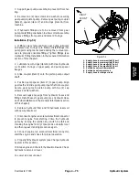
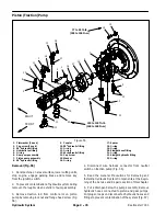
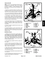
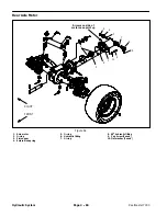
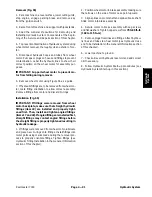
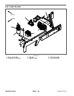
Removal (Fig. 59)
NOTE:
The ports on the manifolds are marked for easy
identification of components. Refer to the Hydraulic
Schematic in Chapter 9 -- Foldout Drawings to identify
the function of the hydraulic lines and cartridge valves
at each port.
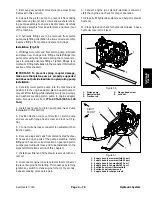
1. Read the General Precautions for Removing and
Installing Hydraulic System Components at the begin-
ning of the Service and Repairs section of this chapter.
2. To prevent contamination of hydraulic system during
manifold removal, thoroughly clean exterior of manifold.
3. If 4WD/2WD control manifold is being removed, la-
bel wire harness electrical connectors that attach to
manifold components. Disconnect harness electrical
connectors from the solenoid valve coil and electrical
sensors (pressure and temperature).
4. Disconnect hydraulic lines from manifold being re-
moved and put caps or plugs on open hydraulic lines
and fittings. Label disconnected hydraulic lines for prop-
er assembly.
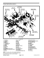
5. Remove hydraulic manifold from the frame using
Figure 59 as guide.
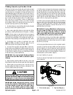
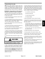
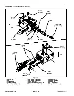
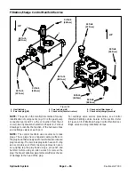
6. If hydraulic fittings are to be removed from control
manifold, mark fitting orientation to allow correct assem-
bly (Figure 60 or 61). Remove fittings from manifold and
discard O--rings.
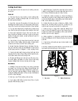
Installation (Fig. 59)
1. If fittings were removed from control manifold, lubri-
cate and place new O--rings onto fittings. Install fittings
into manifold ports using marks made during the remov-
al process to properly orientate fittings. Tighten fittings
(see Hydraulic Fitting Installation in the General Infor-
mation section of this chapter). Refer to Figure 60 or 61
for fitting installation torque.
2. Install hydraulic manifold to the frame using Figure
59 as guide.
3. Remove caps and plugs from fittings and hoses.
Properly connect hydraulic lines to manifold (see Hy-
draulic Hose and Tube Installation in the General Infor-
mation section of this chapter).
4. If 4WD/2WD control manifold was removed, connect
wire harness electrical connectors to the solenoid valve
coil and electrical sensors.
5. Check oil level in hydraulic reservoir and add correct
oil if necessary.
6. Follow Hydraulic System Start--up procedures (see
Hydraulic System Start--up in this section).
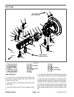
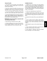
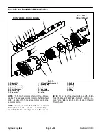
1. 4WD/2WD manifold
2. O--ring
3. 45
o
fitting
4. O--ring
5. 90
o
fitting
6. Straight fitting
7. O--ring
8. O--ring
9. Check fitting
10. O--ring
11. O--ring
12. Straight fitting
13. O--ring
14. Test fitting
15. Dust cap
Figure 60
4
2
6
5
7
3
1
8
9
2
2
4
4
5
6
10
12
11
13
14
15
50 ft--lb
(68 N--m)
75 ft--lb
(101 N--m)
25 ft--lb
(34 N--m)
20 ft--lb
(27 N--m)
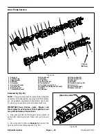
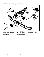
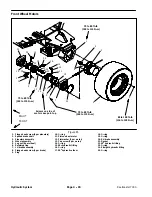
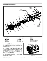
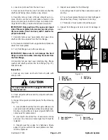
1. Filtration manifold
2. O--ring
3. 90
o
fitting
4. O--ring
5. Straight fitting (3 used)
6. O--ring
7. Straight fitting
8. O--ring
9. O--ring
10. Straight fitting
11. O--ring
12. O--ring
13. Barb fitting
14. O--ring
Figure 61
75 ft--lb
(101 N--m)
2
3
6
8
9
10
11
13
1
5
7
12
14
4
2
5
5
6
6
25 ft--lb
(34 N--m)
50 ft--lb
(68 N--m)
2
75 ft--lb
(101 N--m)
Hydraulic System
Содержание Reelmaster 7000
Страница 2: ...Reelmaster 7000 This page is intentionally blank ...
Страница 4: ...Reelmaster 7000 This page is intentionally blank ...
Страница 10: ...Reelmaster 7000 Page 1 6 Safety This page is intentionally blank ...
Страница 12: ...0 09375 Reelmaster 7000 Page 2 2 Product Records and Maintenance Equivalents and Conversions ...
Страница 34: ...Reelmaster 7000 Page 3 18 Kubota Diesel Engine This page is intentionally blank ...
Страница 36: ...Reelmaster 7000 Hydraulic System Page 4 2 This page is intentionally blank ...
Страница 45: ...Reelmaster 7000 Hydraulic System Page 4 11 This page is intentionally blank Hydraulic System ...
Страница 115: ...Reelmaster 7000 Hydraulic System Page 4 81 This page is intentionally blank Hydraulic System ...
Страница 131: ...Reelmaster 7000 Hydraulic System Page 4 97 This page is intentionally blank Hydraulic System ...
Страница 139: ...Reelmaster 7000 Hydraulic System Page 4 105 This page is intentionally blank Hydraulic System ...
Страница 147: ...Reelmaster 7000 Hydraulic System Page 4 113 This page is intentionally blank Hydraulic System ...
Страница 151: ...Reelmaster 7000 Hydraulic System Page 4 117 This page is intentionally blank Hydraulic System ...
Страница 168: ...Reelmaster 7000 Hydraulic System Page 4 134 This page is intentionally blank ...
Страница 214: ...Reelmaster 7000 Page 5 46 Electrical System This page is intentionally blank ...
Страница 221: ...Reelmaster 7000 Page 6 7 Axles Planetaries and Brakes This page is intentionally blank Axles Planetaries and Brakes ...
Страница 227: ...Reelmaster 7000 Page 6 13 Axles Planetaries and Brakes This page is intentionally blank Axles Planetaries and Brakes ...
Страница 247: ...Reelmaster 7000 Page 7 3 Chassis This page is intentionally blank Chassis ...
Страница 264: ...Reelmaster 7000 Page 7 20 Chassis This page is intentionally blank ...
Страница 271: ...Reelmaster 7000 DPA Cutting Units Page 8 7 This page is intentionally blank DPA Cutting Units ...
Страница 287: ...Reelmaster 7000 DPA Cutting Units Page 8 23 This page is intentionally blank DPA Cutting Units ...
Страница 291: ...Reelmaster 7000 DPA Cutting Units Page 8 27 This page is intentionally blank DPA Cutting Units ...
Страница 295: ...Reelmaster 7000 DPA Cutting Units Page 8 31 This page is intentionally blank DPA Cutting Units ...
Страница 304: ...Reelmaster 7000 DPA Cutting Units Page 8 40 This page is intentionally blank ...
Страница 306: ...Reelmaster 7000 Foldout Drawings Page 9 2 This page is intentionally blank ...
Страница 310: ...Page 9 6 Reelmaster 7000 Main Wire Harness ...
Страница 312: ...Page 9 8 Reelmaster 7000 Seat and Console Wire Harness ...
Страница 314: ...Page 9 10 Reelmaster 7000 Power Center Wire Harness ...