


Reelmaster 7000
Hydraulic System
Page 4 -- 103
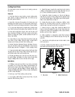
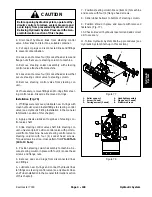
CAUTION
Before opening hydraulic system, operate all hy-
draulic controls to relieve system pressure and
avoid injury from pressurized hydraulic oil. See
Relieving Hydraulic System Pressure in the Gen-
eral Information section of this chapter.
8. Disconnect hydraulic lines from steering control
valve. Allow lines to drain into a suitable container.
9. Put caps or plugs on disconnected lines and fittings
to prevent contamination.
10.Loosen and remove four (4) socket head screws and
flange nuts that secure steering column to machine.
11.Remove steering column assembly with steering
control valve attached from machine.
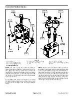
12.Loosen and remove four (4) socket head screws that
secure steering control valve to steering column.
13.Remove steering control valve from steering col-
umn.
14.If necessary, remove fittings and O--rings from steer-
ing control valve. Discard all removed O--rings.
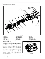
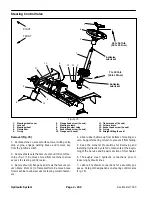
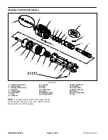
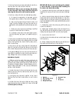
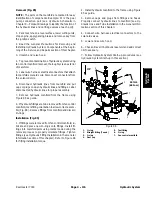
Installation (Fig. 76)
1. If fittings were removed, lubricate new O--rings with
clean hydraulic oil and install fittings to steering control
valve (see Hydraulic Fitting Installation in the General
Information section of this chapter).
2. Apply antiseize lubricant to splines of steering con-
trol valve shaft.
3. Slide steering control valve shaft into steering col-
umn universal joint. Position control valve with ports to-
ward front of machine. Secure steering control valve to
steering column with four (4) socket head screws.
Torque screws in a criss--cross pattern from
7 to 10 ft--lb
(10 to 13 N--m)
.
4. Position steering column assembly to machine. Se-
cure steering column in place with four (4) socket head
screws and flange nuts.
5. Remove caps and plugs from disconnected lines
and fittings.
6. Lubricate new O--rings and connect hydraulic lines
to fittings on steering control valve (see Hydraulic Hose
and Tube Installation in the General Information section
of this chapter).
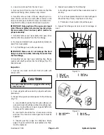
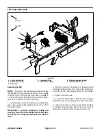
7. Position steering column brace (item 12) to machine
and secure with four (4) flange head screws.
8. Slide rubber bellows to bottom of steering column.
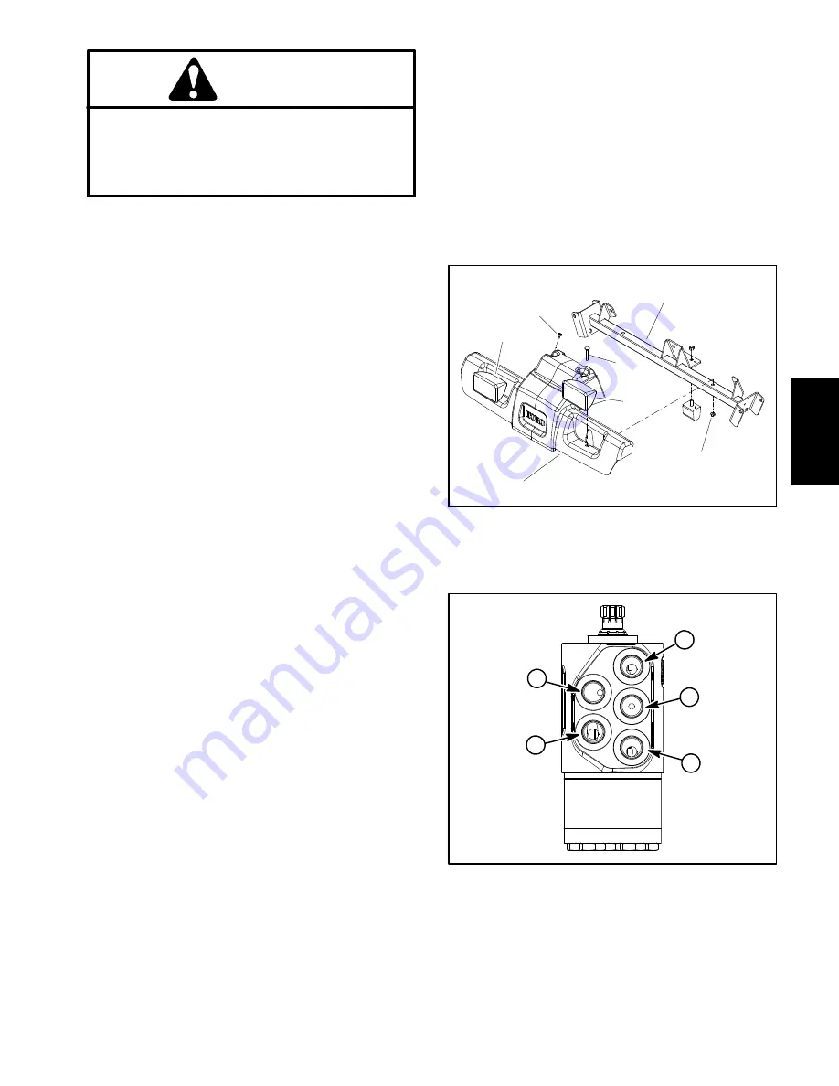
9. Position shroud in place and secure with removed
fasteners (Fig. 77).
10.Check oil level in hydraulic reservoir and add correct
oil if necessary.
11.Follow Hydraulic System Start--up procedures (see
Hydraulic System Start--up in this section).
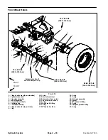
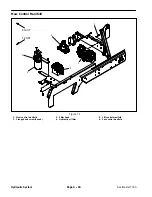
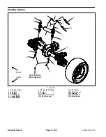
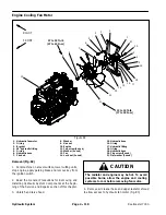
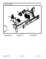
1. Roller support
2. Screw (2 used)
3. Carriage screw (2 used)
4. Headlight assembly
5. Flange nut (2 used)
6. Platform shroud
Figure 77
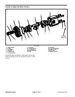
2
3
4
5
6
1
4
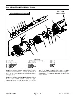
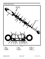
Figure 78
T
R
E
L
P
Hydraulic System
Содержание Reelmaster 7000
Страница 2: ...Reelmaster 7000 This page is intentionally blank ...
Страница 4: ...Reelmaster 7000 This page is intentionally blank ...
Страница 10: ...Reelmaster 7000 Page 1 6 Safety This page is intentionally blank ...
Страница 12: ...0 09375 Reelmaster 7000 Page 2 2 Product Records and Maintenance Equivalents and Conversions ...
Страница 34: ...Reelmaster 7000 Page 3 18 Kubota Diesel Engine This page is intentionally blank ...
Страница 36: ...Reelmaster 7000 Hydraulic System Page 4 2 This page is intentionally blank ...
Страница 45: ...Reelmaster 7000 Hydraulic System Page 4 11 This page is intentionally blank Hydraulic System ...
Страница 115: ...Reelmaster 7000 Hydraulic System Page 4 81 This page is intentionally blank Hydraulic System ...
Страница 131: ...Reelmaster 7000 Hydraulic System Page 4 97 This page is intentionally blank Hydraulic System ...
Страница 139: ...Reelmaster 7000 Hydraulic System Page 4 105 This page is intentionally blank Hydraulic System ...
Страница 147: ...Reelmaster 7000 Hydraulic System Page 4 113 This page is intentionally blank Hydraulic System ...
Страница 151: ...Reelmaster 7000 Hydraulic System Page 4 117 This page is intentionally blank Hydraulic System ...
Страница 168: ...Reelmaster 7000 Hydraulic System Page 4 134 This page is intentionally blank ...
Страница 214: ...Reelmaster 7000 Page 5 46 Electrical System This page is intentionally blank ...
Страница 221: ...Reelmaster 7000 Page 6 7 Axles Planetaries and Brakes This page is intentionally blank Axles Planetaries and Brakes ...
Страница 227: ...Reelmaster 7000 Page 6 13 Axles Planetaries and Brakes This page is intentionally blank Axles Planetaries and Brakes ...
Страница 247: ...Reelmaster 7000 Page 7 3 Chassis This page is intentionally blank Chassis ...
Страница 264: ...Reelmaster 7000 Page 7 20 Chassis This page is intentionally blank ...
Страница 271: ...Reelmaster 7000 DPA Cutting Units Page 8 7 This page is intentionally blank DPA Cutting Units ...
Страница 287: ...Reelmaster 7000 DPA Cutting Units Page 8 23 This page is intentionally blank DPA Cutting Units ...
Страница 291: ...Reelmaster 7000 DPA Cutting Units Page 8 27 This page is intentionally blank DPA Cutting Units ...
Страница 295: ...Reelmaster 7000 DPA Cutting Units Page 8 31 This page is intentionally blank DPA Cutting Units ...
Страница 304: ...Reelmaster 7000 DPA Cutting Units Page 8 40 This page is intentionally blank ...
Страница 306: ...Reelmaster 7000 Foldout Drawings Page 9 2 This page is intentionally blank ...
Страница 310: ...Page 9 6 Reelmaster 7000 Main Wire Harness ...
Страница 312: ...Page 9 8 Reelmaster 7000 Seat and Console Wire Harness ...
Страница 314: ...Page 9 10 Reelmaster 7000 Power Center Wire Harness ...