


Reelmaster 7000
Page 5 -- 24
Electrical System
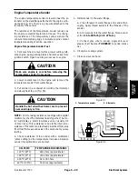
Engine Cooling Fan Switch
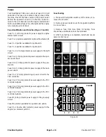
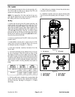
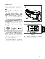
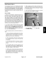
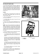
The engine cooling fan switch is located on the outside
of the console arm (Fig. 30). This two (2) position rocker
switch allows the engine cooling fan to run in the normal,
automatic mode or in the manual reverse (momentary)
direction.
Testing
1. Before disconnecting the engine cooling fan switch
for testing, the switch and its circuit wiring should be
tested as a TEC input with the Diagnostic Display (see
Diagnostic Display in the Troubleshooting section of this
chapter). If the Diagnostic Display verifies that cooling
fan switch and circuit wiring
are
functioning correctly, no
further switch testing is necessary. If, however, the Dis-
play determines that cooling fan switch and circuit wiring
are not
functioning correctly, proceed with test.
2. Make sure ignition switch is OFF. Remove key from
ignition switch.
3. Disassemble console arm to gain access to the en-
gine cooling fan switch (see Console Arm Disassembly
in the Service and Repairs section of Chapter 7 -- Chas-
sis).
4. Disconnect harness electrical connector from the
cooling fan switch.
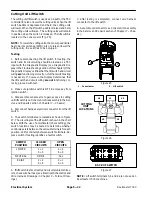
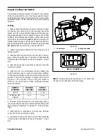
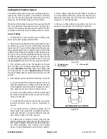
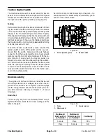
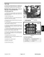
5. With the use of a multimeter (ohms setting), the
switch functions may be tested to determine whether
continuity exists between the various terminals for each
position. The switch terminals are marked as shown in
Figure 31. The circuitry of the cooling fan switch is
shown in the chart below. Verify continuity between
switch terminals.
SWITCH
POSITION
NORMAL
CIRCUITS
OTHER
CIRCUITS
AUTO
2 + 3
5 + 6
MANUAL RE-
VERSE
2 + 1
5 + 4
6. If switch tests correctly and circuit problem still ex-
ists, check wire harness (see Electrical Schematics and
Wire Harness Drawings in Chapter 9 -- Foldout Draw-
ings).
7. After testing is completed, connect wire harness
connector to the cooling fan switch.
8. Assemble console arm (see Console Arm Assembly
in the Service and Repairs section of Chapter 7 -- Chas-
sis).
1. Console arm
2. Cooling fan switch
Figure 30
2
1
Figure 31
BACK OF SWITCH
NOTE:
Cooling fan switch terminals 3, 4, 5 and 6 are
not used on Reelmaster 7000 machines.
Содержание Reelmaster 7000
Страница 2: ...Reelmaster 7000 This page is intentionally blank ...
Страница 4: ...Reelmaster 7000 This page is intentionally blank ...
Страница 10: ...Reelmaster 7000 Page 1 6 Safety This page is intentionally blank ...
Страница 12: ...0 09375 Reelmaster 7000 Page 2 2 Product Records and Maintenance Equivalents and Conversions ...
Страница 34: ...Reelmaster 7000 Page 3 18 Kubota Diesel Engine This page is intentionally blank ...
Страница 36: ...Reelmaster 7000 Hydraulic System Page 4 2 This page is intentionally blank ...
Страница 45: ...Reelmaster 7000 Hydraulic System Page 4 11 This page is intentionally blank Hydraulic System ...
Страница 115: ...Reelmaster 7000 Hydraulic System Page 4 81 This page is intentionally blank Hydraulic System ...
Страница 131: ...Reelmaster 7000 Hydraulic System Page 4 97 This page is intentionally blank Hydraulic System ...
Страница 139: ...Reelmaster 7000 Hydraulic System Page 4 105 This page is intentionally blank Hydraulic System ...
Страница 147: ...Reelmaster 7000 Hydraulic System Page 4 113 This page is intentionally blank Hydraulic System ...
Страница 151: ...Reelmaster 7000 Hydraulic System Page 4 117 This page is intentionally blank Hydraulic System ...
Страница 168: ...Reelmaster 7000 Hydraulic System Page 4 134 This page is intentionally blank ...
Страница 214: ...Reelmaster 7000 Page 5 46 Electrical System This page is intentionally blank ...
Страница 221: ...Reelmaster 7000 Page 6 7 Axles Planetaries and Brakes This page is intentionally blank Axles Planetaries and Brakes ...
Страница 227: ...Reelmaster 7000 Page 6 13 Axles Planetaries and Brakes This page is intentionally blank Axles Planetaries and Brakes ...
Страница 247: ...Reelmaster 7000 Page 7 3 Chassis This page is intentionally blank Chassis ...
Страница 264: ...Reelmaster 7000 Page 7 20 Chassis This page is intentionally blank ...
Страница 271: ...Reelmaster 7000 DPA Cutting Units Page 8 7 This page is intentionally blank DPA Cutting Units ...
Страница 287: ...Reelmaster 7000 DPA Cutting Units Page 8 23 This page is intentionally blank DPA Cutting Units ...
Страница 291: ...Reelmaster 7000 DPA Cutting Units Page 8 27 This page is intentionally blank DPA Cutting Units ...
Страница 295: ...Reelmaster 7000 DPA Cutting Units Page 8 31 This page is intentionally blank DPA Cutting Units ...
Страница 304: ...Reelmaster 7000 DPA Cutting Units Page 8 40 This page is intentionally blank ...
Страница 306: ...Reelmaster 7000 Foldout Drawings Page 9 2 This page is intentionally blank ...
Страница 310: ...Page 9 6 Reelmaster 7000 Main Wire Harness ...
Страница 312: ...Page 9 8 Reelmaster 7000 Seat and Console Wire Harness ...
Страница 314: ...Page 9 10 Reelmaster 7000 Power Center Wire Harness ...