


Greensmaster 3300/3400
Hydraulic System
Page 5 -- 41
The steering/lift relief valve pressure test should be per-
formed to make sure that the relief pressure for the
steering and lift circuits is correct.
Procedure for Steering/Lift Relief Valve Pressure
Test:
1. Make sure hydraulic oil is at normal operating tem-
perature by operating the machine for approximately ten
(10) minutes.
2. Park machine on a level surface with the cutting units
lowered. Make sure engine is off and the parking brake
is engaged. Make sure the hydraulic tank is full.
CAUTION
Prevent personal injury and/or damage to equip-
ment. Read all WARNINGS, CAUTIONS and Pre-
cautions for Hydraulic Testing at the beginning
of this section.
NOTE:
The steering/lift relief valve is in series with the
traction charge relief valve. Traction charge pressure
will therefore affect steering/lift relief valve pressure.
3. Measure and record charge relief valve pressure
(see Charge Relief Valve Pressure Test in this section).
4. Remove right side cover next to operator seat to al-
low access to lift control manifold.
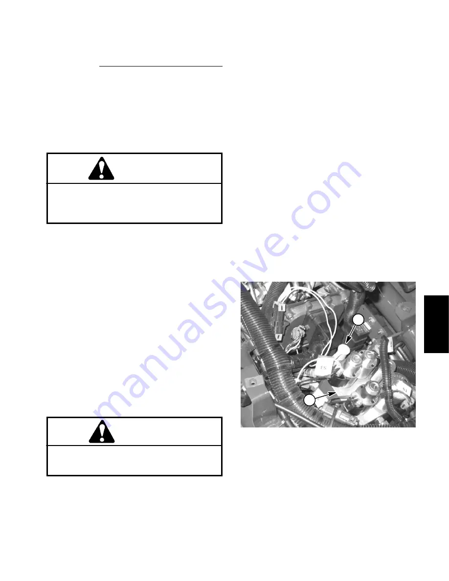
5. Install 5000 PSI (350 bar) pressure gauge with hy-
draulic hose attached to lift control manifold test port (G)
(Fig. 22).
6. Make sure that traction pedal and joystick are in neu-
tral and the parking brake is engaged.
7. Start engine and run at low idle speed. Check for hy-
draulic leakage and correct before proceeding with test.
8. Move throttle so engine is running at high idle speed.
CAUTION
While measuring steering/lift relief valve pres-
sure, do not allow circuit pressure to exceed
1400 PSI (82.8 bar).
9. Watch the pressure gauge and move the joystick to
the
raise
position. Momentarily hold the joystick with the
cutting units fully raised causing the relief valve to open.
Release the joystick when the relief pressure is identi-
fied.
10.Shut off engine. Record pressure at which the relief
valve opens.
11. Steering/lift valve pressure should be approximately
1160 PSI (80 bar) higher than the charge relief valve
pressure
(e.g. if the charge relief valve pressure is 125
PSI (8.6 bar), the steering/lift relief valve pressure
should be approximately 1285 PSI (88.6 bar)).
12.If steering/lift relief valve pressure is incorrect, in-
spect relief valve located in the power steering valve
(see Power Steering Valve Service in the Service and
Repairs section of this Chapter). Clean relief valve or
service power steering valve as needed.
NOTE:
The lower cutting units relief valve (RV) pres-
sure can also be measured with pressure gauge posi-
tioned as described in this test (see Lower Cutting Units
Relief Valve (RV) Pressure Test in this section).
13.When testing is complete, disconnect pressure
gauge from lift control manifold test port. Install dust cap
to test port fitting. Install right side cover.
1. Lift control manifold
2. Test port
Figure 22
2
1
Hy
draulic
Sy
st
em
Содержание 04510 Greensmaster 3300 TriFlex
Страница 2: ...Greensmaster 3300 3400 This page is intentionally blank ...
Страница 4: ...Greensmaster 3300 3400 This page is intentionally blank ...
Страница 6: ...Greensmaster 3300 3400 This page is intentionally blank ...
Страница 14: ...0 09375 Greensmaster 3300 3400 Page 2 2 Product Records and Maintenance Equivalents and Conversions ...
Страница 24: ...Greensmaster 3300 Page 3 6 Gasoline Engine This page is intentionally blank ...
Страница 38: ...Greensmaster 3400 Page 4 4 Diesel Engine This page is intentionally blank ...
Страница 54: ...Greensmaster 3300 3400 Hydraulic System Page 5 2 This page is intentionally blank ...
Страница 63: ...Greensmaster 3300 3400 Hydraulic System Page 5 11 This page is intentionally blank Hydraulic System ...
Страница 83: ...Greensmaster 3300 3400 Hydraulic System Page 5 31 This page is intentionally blank Hydraulic System ...
Страница 121: ...Greensmaster 3300 3400 Hydraulic System Page 5 69 This page is intentionally blank Hydraulic System ...
Страница 125: ...Greensmaster 3300 3400 Hydraulic System Page 5 73 This page is intentionally blank Hydraulic System ...
Страница 131: ...Greensmaster 3300 3400 Hydraulic System Page 5 79 This page is intentionally blank Hydraulic System ...
Страница 137: ...Greensmaster 3300 3400 Hydraulic System Page 5 85 This page is intentionally blank Hydraulic System ...
Страница 155: ...Greensmaster 3300 3400 Hydraulic System Page 5 103 This page is intentionally blank Hydraulic System ...
Страница 167: ...Greensmaster 3300 3400 Hydraulic System Page 5 115 This page is intentionally blank Hydraulic System ...
Страница 170: ...Greensmaster 3300 3400 Hydraulic System Page 5 118 This page is intentionally blank ...
Страница 172: ...Greensmaster 3300 3400 Page 6 2 Electrical System This page is intentionally blank ...
Страница 181: ...Greensmaster 3300 3400 Page 6 11 Electrical System This page is intentionally blank Electrical System ...
Страница 223: ...Greensmaster 3300 3400 Page 6 53 Electrical System This page is intentionally blank Electrical System ...
Страница 230: ...Greensmaster 3300 3400 Page 6 60 Electrical System This page is intentionally blank ...
Страница 265: ...Greensmaster 3300 3400 DPA Cutting Units Page 8 9 This page is intentionally blank DPA Cutting Units ...
Страница 279: ...Greensmaster 3300 3400 DPA Cutting Units Page 8 23 This page is intentionally blank DPA Cutting Units ...
Страница 303: ...Greensmaster 3300 3400 Groomer Page 9 13 This page is intentionally blank Groomer ...
Страница 318: ...Greensmaster 3300 3400 Page 10 2 Foldout Drawings This page is intentionally blank ...
Страница 332: ...Page 10 16 This page is intentionally blank ...


