


Greensmaster 3300/3400
Page 6 -- 40
Electrical System
Hydraulic Solenoid Valve Coils
The Greensmaster hydraulic control manifolds use sev-
eral hydraulic solenoid valve coils for system control.
The lift manifold includes four (4) solenoid valves and
the mow manifold includes a single solenoid valve. On
machines equipped with the Turf Guardian
TM
Leak De-
tector, the leak detector manifold includes a single sole-
noid valve. When the solenoid coils are energized,
hydraulic valve shift occurs to control hydraulic circuit
flow. Testing of the coils can be done with the coil
installed on the hydraulic valve.
Testing
NOTE:
Before disconnecting and testing solenoid
valve coils, test the TEC controller outputs with the Diag-
nostic Display (see Diagnostic Display in the Trouble-
shooting section of this chapter). If the Diagnostic
Display verifies that the TEC outputs
are
functioning
correctly, consider that a problem with the solenoid
valve coil or circuit wiring may exist. An open or shorted
controller output (e.g. a failed solenoid valve coil, an un-
plugged connector or a broken wire) cannot be detected
with the Diagnostic Display. Conversely, if the Diagnos-
tic Display verifies that the TEC outputs
are not
func-
tioning correctly, consider that a problem with controller
inputs, controller fuses or the TEC controller may exist.
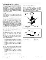
1. Park machine on level surface, lower cutting units,
stop engine, apply parking brake and remove key from
ignition switch.
2. Determine solenoid coil(s) that are to be tested and
locate coil on correct hydraulic manifold:
A. Remove right side cover next to operator seat to
allow access to lift control manifold.
B. Remove left side cover next to operator seat to al-
low access to mow control manifold.
C. To gain access to leak detector manifold, see
Leak Detector Solenoid Valve Assembly in the Ser-
vice and Repairs section of Chapter 5 -- Hydraulic
System.
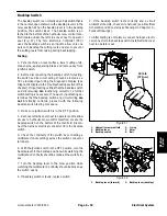
3. Disconnect harness electrical connector from hy-
draulic solenoid valve coil that is to be tested (Figs. 49,
50 or 51).
NOTE:
Prior to taking small resistance readings with a
digital multimeter, short the meter test leads together.
The meter may display a small resistance value (usually
0.5 ohms or less). This resistance is due to the internal
resistance of the meter and test leads. Subtract this val-
ue from the measured value of the solenoid coil being
testing.
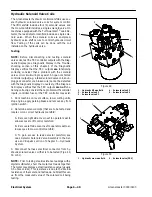
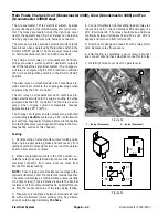
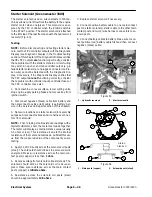
1. Hydraulic lift manifold
2. Solenoid valve S1
3. Solenoid valve S2
4. Solenoid valve S3
5. Solenoid valve S4
Figure 49
2
4
5
3
1
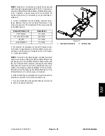
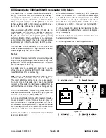
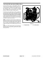
1. Hydraulic mow manifold
2. Solenoid valve (PRV)
Figure 50
2
1
Содержание 04510 Greensmaster 3300 TriFlex
Страница 2: ...Greensmaster 3300 3400 This page is intentionally blank ...
Страница 4: ...Greensmaster 3300 3400 This page is intentionally blank ...
Страница 6: ...Greensmaster 3300 3400 This page is intentionally blank ...
Страница 14: ...0 09375 Greensmaster 3300 3400 Page 2 2 Product Records and Maintenance Equivalents and Conversions ...
Страница 24: ...Greensmaster 3300 Page 3 6 Gasoline Engine This page is intentionally blank ...
Страница 38: ...Greensmaster 3400 Page 4 4 Diesel Engine This page is intentionally blank ...
Страница 54: ...Greensmaster 3300 3400 Hydraulic System Page 5 2 This page is intentionally blank ...
Страница 63: ...Greensmaster 3300 3400 Hydraulic System Page 5 11 This page is intentionally blank Hydraulic System ...
Страница 83: ...Greensmaster 3300 3400 Hydraulic System Page 5 31 This page is intentionally blank Hydraulic System ...
Страница 121: ...Greensmaster 3300 3400 Hydraulic System Page 5 69 This page is intentionally blank Hydraulic System ...
Страница 125: ...Greensmaster 3300 3400 Hydraulic System Page 5 73 This page is intentionally blank Hydraulic System ...
Страница 131: ...Greensmaster 3300 3400 Hydraulic System Page 5 79 This page is intentionally blank Hydraulic System ...
Страница 137: ...Greensmaster 3300 3400 Hydraulic System Page 5 85 This page is intentionally blank Hydraulic System ...
Страница 155: ...Greensmaster 3300 3400 Hydraulic System Page 5 103 This page is intentionally blank Hydraulic System ...
Страница 167: ...Greensmaster 3300 3400 Hydraulic System Page 5 115 This page is intentionally blank Hydraulic System ...
Страница 170: ...Greensmaster 3300 3400 Hydraulic System Page 5 118 This page is intentionally blank ...
Страница 172: ...Greensmaster 3300 3400 Page 6 2 Electrical System This page is intentionally blank ...
Страница 181: ...Greensmaster 3300 3400 Page 6 11 Electrical System This page is intentionally blank Electrical System ...
Страница 223: ...Greensmaster 3300 3400 Page 6 53 Electrical System This page is intentionally blank Electrical System ...
Страница 230: ...Greensmaster 3300 3400 Page 6 60 Electrical System This page is intentionally blank ...
Страница 265: ...Greensmaster 3300 3400 DPA Cutting Units Page 8 9 This page is intentionally blank DPA Cutting Units ...
Страница 279: ...Greensmaster 3300 3400 DPA Cutting Units Page 8 23 This page is intentionally blank DPA Cutting Units ...
Страница 303: ...Greensmaster 3300 3400 Groomer Page 9 13 This page is intentionally blank Groomer ...
Страница 318: ...Greensmaster 3300 3400 Page 10 2 Foldout Drawings This page is intentionally blank ...
Страница 332: ...Page 10 16 This page is intentionally blank ...


