


Greensmaster 3300/3400
Hydraulic System
Page 5 -- 15
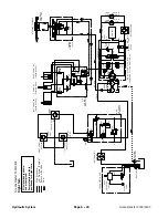
Lower Cutting Units
The tandem gear pump is directly coupled to the piston
(traction) pump. The rear gear pump section supplies
hydraulic flow for the steering circuit (priority flow), for
raising and lowering the cutting units and for the traction
charge circuit. The gear pump takes its suction from the
hydraulic reservoir. Maximum circuit pressure of 1160
PSI (80 bar) is limited by the relief valve located in the
power steering valve.
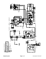
The lift control manifold includes four (4) electrically op-
erated solenoid valves. Solenoid valve S1 causes circuit
flow to by--pass the lift cylinders when de--energized
and directs flow to the cylinders when energized. Direc-
tional solenoid valve S2 is used to direct oil flow to raise
the cutting units when de--energized and lower them
when energized. When energized, solenoid valve S3 al-
lows hydraulic flow to and from the front cutting unit lift
cylinders (#2 and #3) and prevents oil passage to and
from the lift cylinders when de--energized. When ener-
gized, solenoid valve S4 allows hydraulic flow to and
from the center cutting unit lift cylinder (#1) and prevents
oil passage to and from the lift cylinder when de--ener-
gized.
The console arm joystick is used to raise and lower the
cutting units. The joystick acts as an input to the TEC
controller to send electrical outputs to appropriate lift
control manifold solenoid coils in order to raise or lower
the cutting units.
While operating the machine during conditions of not
raising or lowering the cutting units (joystick in the neu-
tral (center) position), all of the lift manifold solenoid
valves (S1, S2, S3 and S4) are de--energized. Flow from
the rear gear pump section is directed through the pow-
er steering valve, de--energized solenoid valve S1 in the
lift control manifold, oil filter and to the traction charge
circuit. Flow in excess of charge circuit needs then re-
turns to the gear pump input.
Lower Cutting Units
When the joystick is moved to the lower position, the
Toro Electronic Controller (TEC) energizes all of the lift
control manifold solenoid valves for approximately three
(3) seconds. This time frame ensures that the cutting
units will be fully lowered to allow them to float during op-
eration. The controller also provides a short delay in en-
ergizing solenoid valve S4 which delays the lowering of
the center cutting unit (#1).
Energized lift manifold solenoids S1 and S2 direct circuit
flow toward the lift cylinders in the correct direction to
lower the cutting units. The front lift cylinders extend to
lower the cutting units while the center lift cylinder re-
tracts to lower the cutting unit. Hydraulic pressure
against the lift cylinder pistons moves their shafts caus-
ing the cutting units to lower. At the same time, the lift cyl-
inder pistons push the hydraulic fluid out of the cylinders
to energized solenoid valves S3 (front lift cylinders) and
S4 (center lift cylinder). Return flow continues through
energized solenoid valve S2, to the oil filter and then to
the traction charge circuit.
Lowering speed for each of the front cutting units (#2
and #3) is controlled by a 0.028 orifice (OR2 and OR3)
in the lift control manifold. A 0.037 orifice (OR1) controls
lowering speed for the center cutting unit (#1).
If the lift cylinders should reach the end of their stroke
while the lift manifold solenoids are still energized, lift cir-
cuit pressure will increase. The lift circuit lower relief
valve (RV) in the lift control manifold allows lift circuit
pressure to be limited to 400 PSI (27.6 bar) while lower-
ing the cutting units.
NOTE:
Adjustment of the lift control manifold lift circuit
lower relief valve (RV) is not recommended.
When the lift control manifold solenoid valves are de--
energized by the TEC controller, spring action returns
the valves to their original position stopping lift cylinder
movement. The lift cylinder position is locked in place
since there is no complete circuit of flow to and from the
lift cylinders. Hydraulic flow by--passes the lift cylinders
and is routed to the oil filter and charge circuit.
Hydraulic System
Содержание 04510 Greensmaster 3300 TriFlex
Страница 2: ...Greensmaster 3300 3400 This page is intentionally blank ...
Страница 4: ...Greensmaster 3300 3400 This page is intentionally blank ...
Страница 6: ...Greensmaster 3300 3400 This page is intentionally blank ...
Страница 14: ...0 09375 Greensmaster 3300 3400 Page 2 2 Product Records and Maintenance Equivalents and Conversions ...
Страница 24: ...Greensmaster 3300 Page 3 6 Gasoline Engine This page is intentionally blank ...
Страница 38: ...Greensmaster 3400 Page 4 4 Diesel Engine This page is intentionally blank ...
Страница 54: ...Greensmaster 3300 3400 Hydraulic System Page 5 2 This page is intentionally blank ...
Страница 63: ...Greensmaster 3300 3400 Hydraulic System Page 5 11 This page is intentionally blank Hydraulic System ...
Страница 83: ...Greensmaster 3300 3400 Hydraulic System Page 5 31 This page is intentionally blank Hydraulic System ...
Страница 121: ...Greensmaster 3300 3400 Hydraulic System Page 5 69 This page is intentionally blank Hydraulic System ...
Страница 125: ...Greensmaster 3300 3400 Hydraulic System Page 5 73 This page is intentionally blank Hydraulic System ...
Страница 131: ...Greensmaster 3300 3400 Hydraulic System Page 5 79 This page is intentionally blank Hydraulic System ...
Страница 137: ...Greensmaster 3300 3400 Hydraulic System Page 5 85 This page is intentionally blank Hydraulic System ...
Страница 155: ...Greensmaster 3300 3400 Hydraulic System Page 5 103 This page is intentionally blank Hydraulic System ...
Страница 167: ...Greensmaster 3300 3400 Hydraulic System Page 5 115 This page is intentionally blank Hydraulic System ...
Страница 170: ...Greensmaster 3300 3400 Hydraulic System Page 5 118 This page is intentionally blank ...
Страница 172: ...Greensmaster 3300 3400 Page 6 2 Electrical System This page is intentionally blank ...
Страница 181: ...Greensmaster 3300 3400 Page 6 11 Electrical System This page is intentionally blank Electrical System ...
Страница 223: ...Greensmaster 3300 3400 Page 6 53 Electrical System This page is intentionally blank Electrical System ...
Страница 230: ...Greensmaster 3300 3400 Page 6 60 Electrical System This page is intentionally blank ...
Страница 265: ...Greensmaster 3300 3400 DPA Cutting Units Page 8 9 This page is intentionally blank DPA Cutting Units ...
Страница 279: ...Greensmaster 3300 3400 DPA Cutting Units Page 8 23 This page is intentionally blank DPA Cutting Units ...
Страница 303: ...Greensmaster 3300 3400 Groomer Page 9 13 This page is intentionally blank Groomer ...
Страница 318: ...Greensmaster 3300 3400 Page 10 2 Foldout Drawings This page is intentionally blank ...
Страница 332: ...Page 10 16 This page is intentionally blank ...


