10
11
EN
EN
SLIT LAMP TSL-7000Z by TOMEY
SLIT LAMP TSL-7000Z by TOMEY
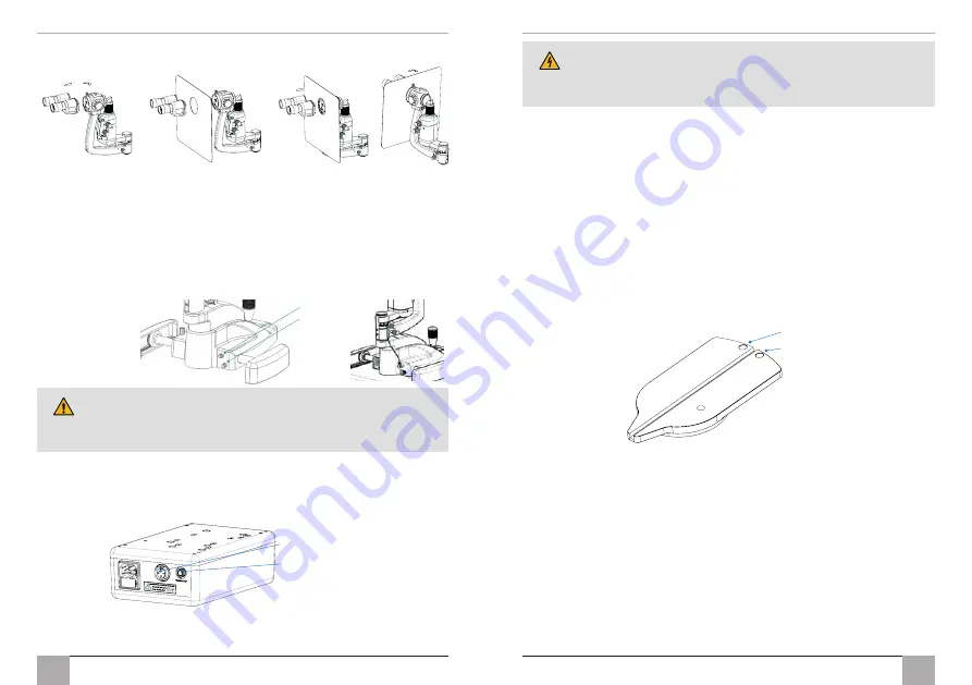
3. Attach the breath shield as indicated in the images below.
5.3 CABLE ATTACHMENT PROCEDURE
1. Connect the power cables.
a) Chinrest fi xation light cable to power supply unit.
b) (3 pin) cable from power supply unit to slit lamp base assembly.
c) (4 pin) main lamp cable from bottom of the illumination assembly to the slit lamp
base assembly.
d) Ensure cables are routed to allow free movement of the XYZ base and to be clear of
the patients.
If your Slit Lamp was not supplied with a transformer (Part #3020-P-5040-
TOM), make sure that the power connection is compatible with the
specifi cations in this manual and is connected by a qualifi ed technician to
an available and suitable power supply,
see section 9.4 Power Supply page 20.
2. If the Tomey Slit Lamp is used with a power supply or cables other than those supplied,
this may result in increased emissions or decreased immunity of the Tomey Slit Lamp in
relation to EMC performance.
3. Connect the mains power to the Slit Lamp transformer using the power lead provided.
4. To isolate from the mains supply unplug the mains plug from the wall socket. Ensure
that the product is positioned so that it is easily accessible.
4 pin
3 pin
3 pin to 3 pin
Fixation light socket
Only a hospital grade 3-conductor electrical power supply cable must be
used. For USA and Canada: Detachable power supply cord set, UL listed,
type SJE, SJT or SJO, 3-conductor, not smaller than 18 AWG. Plug, cable
and ground lead connection of the socket have to be in perfect condition.
5.4 FITTING APPLANATION TONOMETERS, T TYPE AND R TYPES
Tomey Applanation Tonometer (T-TYPE)
1. Position the guide plate in the tonometer / test bar support hole on the slit lamp.
2. Lift Tonometer out of the packaging and assemble it by inserting the pin on its base
into one of the two possible openings (for right or left eye) on the horizontal guide
plate above the slit lamp axis. These positions are related to the microscope optics and
observation can be made either through the right or the left eye-piece.
The tonometer will slip easily onto the support plate; stability is assured by the locking pins.
3. To obtain an image as clear and as free of refl exes as possible, the angle between the
illumination and the microscope should be about 60° and the slit diaphragm should be
fully opened.
4. When not in use the Tonometer should be removed from the Slit Lamp and placed
securely back in the packaging or a suitable location.
Applanation Tonometer ‘Tomey Fixed’ (R-TYPE)
This instrument is for those who wish the tonometer to remain permanently on the slit lamp.
5. Mount the plate for the tonometer onto the microscope body using the securing screw.
6. Mount the Tonometer onto the mounting post ensuring the grub screws are loose.
7. Swing the Tonometer arm forward in front of the microscope for examination. Rotate
the Tonometer body until the prism is in the centre of the view through the eyepiece.
Carefully tighten the two retaining grub screws in turn until the Tonometer is secure on
the mount and the prism is in the centre of view.
8. To obtain an image as clear and as free of refl exes as possible, the angle between the
illumination and the microscope should be about 60° and the slit diaphragm should be
fully opened.
9. When not in use the tonometer arm should be swung up against the protection plate.
Right eye
Left eye


