11
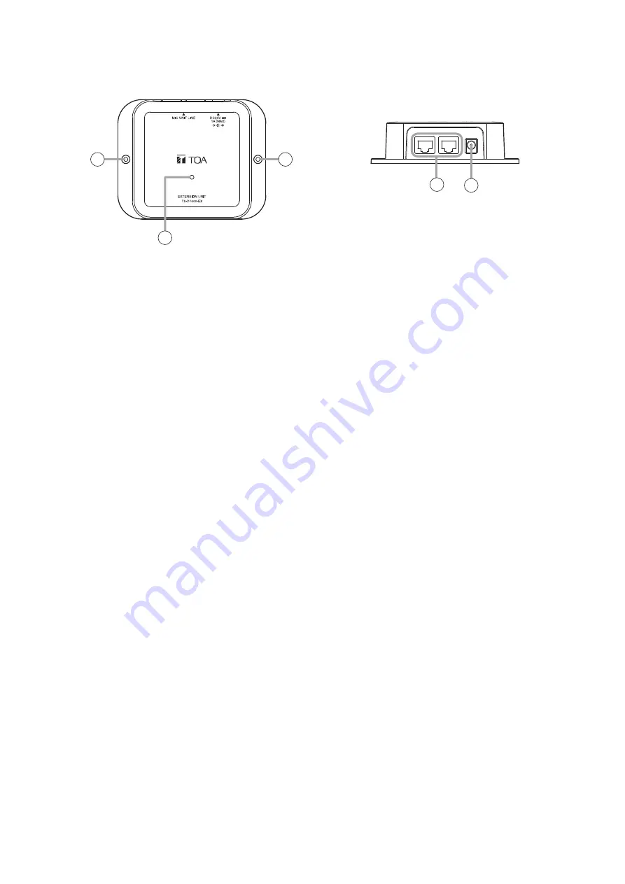
5.3. TS-D1000-EX Extension Unit
[Top]
[Rear]
1
2
2
3
4
1. Power indicator (Green)
Lights when power is switched ON.
This indicator interlocks with the Master control
unit’s power switch operation when the Master
control or the Sub control unit, and the supplied AC
adapter are connected to the Extension unit.
2. Mounting holes
Mounting holes for 3 mm (0.12") diameter screws.
Use these holes when attaching the unit to a wall
or other surface.
Note
Please note that the mounting screws themselves
are not supplied with the unit.
3. Conference unit connection terminals
RJ45 × 2
When extending the distance between two
Conference units, connect to either of these
terminals using a CAT5e STP LAN cable.
Tip
Either terminal may be used for connection.
4. DC inlet
Insert the power plug from the unit’s supplied AC
adapter into this inlet.


