27
9.3. Conference Unit and Sub Control Unit Connections
(3) Conference unit Connection
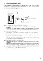
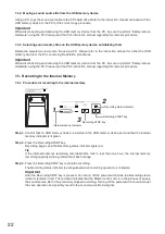
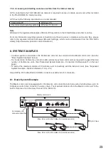
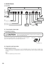
Connect Conference units to the TS-D1000-MU Master control unit using a CAT5e STP LAN cable fitted
with RJ45 connectors at both ends (refer to "SYSTEM EXAMPLES" on p. 23).
(4) Sub control unit Connection
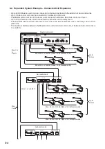
Connect Sub control units to the TS-D1000-MU using a CAT5e STP LAN cable fitted with the RJ45 connector
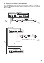
at both ends (refer to "Expanded System Example – Connected Unit Expansion" on p. 24).
9.4. LAN Connection
(5) LAN Connection
Connect the TS-D1000-MU to the network.
Connectable network interface: 10 BASE-T, 100BASE-TX
9.5. External Device Connections
(6) External Recording Device Connection
The spoken contents of the conference can be recorded by connecting a recording device, such as an IC
recorder.
Recording output specifications: –10 dB*, 10 kΩ, unbalanced, RCA pin jack (monaural)
Note
The same sound output is directed to both left and right channels.
(7) External Amplifier Connection
Output from the TS-D1000-MU can be input to an external amplifier or mixer.
Line output specifications: –10 dB*, 10 kΩ, unbalanced, phone jack (monaural)
(8) External Processor Connection
In cases where feedback cannot be controlled by the internal FBS function, a graphic equalizer or other
external processor can be connected for use.
External processor output (SEND) specifications: −10 dB*, 10 kΩ, unbalanced, RCA pin jack
External processor input (RETURN) specifications: −10 dB*, 10 kΩ, unbalanced, RCA pin jack
(9) Video Conference System Connection
Video conference systems can also be connected and used.
Video conference output (OUT) specifications: −10 dB*, 10 kΩ, unbalanced, RCA pin jack
Video conference input (IN) specifications:
−10 dB*, 10 kΩ, unbalanced, RCA pin jack
(10) Microphone Connection
An external microphone can be connected to this jack for amplified output at all Conference units.
Microphone input specifications:−54 dB*, 600 Ω, unbalanced, phone jack (monaural)
* 0 dB = 1 V


