


5
3-UNPACKING & SETUP
Only skilled personnel who are familiar with the lift and this manual shall be allowed to
carry out, lifting, handling, transport and unpacking operations.
When the lift is delivered, carefully unpack the lift making sure all the parts have been
included. Check for possible damages due to transport and storage; verify that what is
specified in the confirmation of order is included. In case of damage in transit, the customer
must immediately inform the carrier of the problem.
Remove the lift and all parts from delivery pallet and place on a clean, solid, flat surface.
Packages must be opened paying attention not to cause damage to people (keep a safe
distance when opening straps) and parts of the lift (be careful the objects do not
drop from the package when opening.)
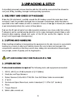
LIFT AND HANDLE ONLY ONE PACKAGE AT A TIME
3.1 DELIVERY AND CHECK OF PACKAGES
3.2 LIFTING AND HANDLING
3.3 PREPARATION
When loading/unloading or transporting the equipment to the site, be sure to use suitable
loading (e.g. cranes, trucks) and hoisting means. Be sure to hoist and transport the
components securely so that they cannot drop, taking into consideration the package’s
size, weight, center of gravity, and its fragile parts.
Professional installation is required.
The following tools and equipment are needed:
1.
ISO-32, AW-32, or AW-46 hydraulic oil (2.5 Gallons)
2. Chalk line and Tape Measure
3.
Rotary Hammer Drill with 3/4” Drill Bit. Core Drill Rebar Cutter recommended
4. 4’ Level
5.
Sockets and Open Wrench set, metric & standard (1-1/8”for 3/4” Anchors)
6. Pliers
7.
Torque Wrench
8.
Metric allen wrench set
Содержание HD2P-10000AC-D
Страница 27: ...23 FIG 2 EXPLODED PARTS VIEW 43 43 1 37A 37B 43 43 1 37A 37B...
Страница 29: ...25 FIG 3 ELECTRICAL POWER SUPPLY KM POWER SUPPLY 0 M CONTACTOR CONTACTOR...
Страница 31: ...27 FIG 5 DIMENSIONS 38 58 3 4 32 1 2 48 1 2 108 145 144 3 4 min 5 max 72 117 3 8 17...
Страница 34: ......
Страница 35: ...NOTES...