


8
6-INSTALLATION INSTRUCTIONS
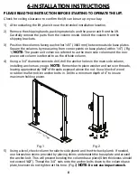
PLEASE READ THIS INSTRUCTION BEFORE STARTING TO OPERATE THE LIFT.
1) After unloading the lift, place it near the intended installation location.
2) Remove the shipping bands, packing materials and the power unit from the lift.
Carefully remove the parts from the column inside. Unbolt the column from the
shipping brackets.
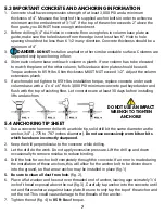
3) Position the columns facing each other 145” (3683 mm) between outside base plates.
Square the columns by measuring from corner points on base plates (within 1/4”). (Fig.
1)
NOTE:
The power unit column is referred to as the main side column and the non-
power unit column is referred to as the offside column.
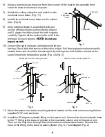
4) Using a 3/4” diameter concrete drill, drill the anchor holes in the main side column,
installing anchors as you go.
NOTE:
Remember to place washer and nut over threads,
leaving approximately
1/4”
of threads exposed above the nut. Use a block of wood
or rubber mallet to drive anchor bolts in. Drill to a minimum depth of 4” to insure
maximum holding power.
5) Using a level, check column for side-to-side plumb and front-to-back plumb. If needed,
use horseshoe shims provided by placing shims underneath the base plate and around
the anchor bolt. This will prevent bending the column base plate (Shim thickness should
not exceed
1/2”
). Thread the 3/4” nuts onto the anchor bolts down to the column base
plate, however do not tighten at this time. (Fig.2)
NOTE:
Do not use impact wrench.
Check for ceiling clearance to confirm the lift can be set up in your bay.
$
%
PP
Fig. 1
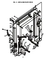
Fig. 2
Содержание HD2P-10000AC-D
Страница 27: ...23 FIG 2 EXPLODED PARTS VIEW 43 43 1 37A 37B 43 43 1 37A 37B...
Страница 29: ...25 FIG 3 ELECTRICAL POWER SUPPLY KM POWER SUPPLY 0 M CONTACTOR CONTACTOR...
Страница 31: ...27 FIG 5 DIMENSIONS 38 58 3 4 32 1 2 48 1 2 108 145 144 3 4 min 5 max 72 117 3 8 17...
Страница 34: ......
Страница 35: ...NOTES...