


10
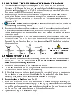
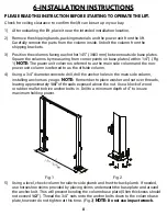
13) Raise the carriages (approximately 28” from the ground)
so that they are resting on the first safety lock position
(Fig. 8). Connect the equalizing cables as shown in the
cable diagram.
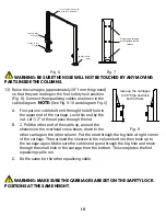
NOTE:
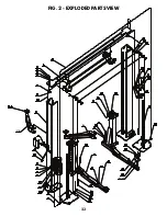
(See Fig. 9-10 and diagram Fig. 2)
A.
First put one cable bolt end through the left hole in
the upper end of the carriage. Lock this end by the
nut. Let 1/2” of thread pass through the nut.
B.
2. Pull the other end of the cable up, around the
sheaves on the overhead cross beam, down to the
other carriage in the other column. Put the stud through the big hole at right corner
of the carriage. Then around the sheaves in the column bottom, then back up to
the carriage again. Make sure the cable stud goes through the big hole and move
through the small hole in the carriage from the bottom. This completes the first
equalizing cable run.
C.
Do the same for the other equalizing cable.
Fig. 6
Fig. 7
Fig. 8
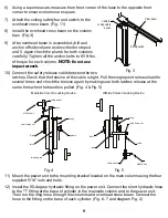
hydraulic fitting
90 degree
'T' fitting on the
cylinder
90 degree hose
fitting
The hose should be routed
through the metal guides
Route hose through
metal guides inside
column
WARNING: BE SURE THE HOSE WILL NOT BE TOUCHED BY ANY MOVING
PARTS INSIDE THE COLUMNS.
WARNING: MAKE SURE THE CARRIAGES ARE SET ON THE SAFETY LOCK
POSITIONS AT THE SAME HEIGHT.
raise up the carriages
to 28" high and lock
both of them
Содержание HD2P-10000AC-D
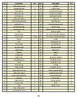
Страница 27: ...23 FIG 2 EXPLODED PARTS VIEW 43 43 1 37A 37B 43 43 1 37A 37B...
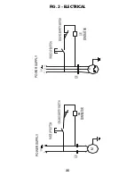
Страница 29: ...25 FIG 3 ELECTRICAL POWER SUPPLY KM POWER SUPPLY 0 M CONTACTOR CONTACTOR...
Страница 31: ...27 FIG 5 DIMENSIONS 38 58 3 4 32 1 2 48 1 2 108 145 144 3 4 min 5 max 72 117 3 8 17...
Страница 34: ......
Страница 35: ...NOTES...