Titan Lifts HD2P-10000AC-D Скачать руководство пользователя страница 13

9

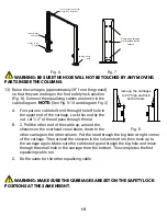
6)  Using a tape measure, measure from front corner of the base to the opposite front 

corner to ensure columns are square.

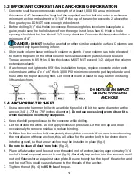
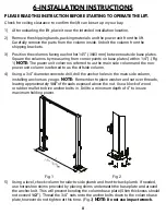
7)  Attach the ceiling safety bar and switch to the 

overhead cross beam. (Fig. 11)

8) 

Install the overhead cross beam on the column 

tops. (Fig. 3) 

9)  After overhead beam is assembled, drill and 

anchor offside column as described in steps 4 

and 5. Again check the plumb for both columns 

carefully. Tighten all the anchor bolts to 85 ft-lbs. 

of torque for each column. 

NOTE:


Do not use 

impact wrench.

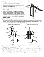
10)  Connect the safety release cable between the two 

latches. Check that the tension of the cable is tight. Pull the single point release handle 

several times and check the tension again by making sure both latches release at the 

same time when the handle is pulled. (Fig. 4 & Fig. 5)

11)  Mount the power unit to the mounting bracket located on the main column using the four 

supplied 5/16” nuts and bolts.

12) 

Install the 90-degree hydraulic fitting on the power unit. Connect the short hydraulic hose 

to the “T” fitting at the base of cylinder in the mainside column and to the power unit. 

Then run the long hose through the columns and overhead cross beam. Connect the 

hose to the fitting on the base of each cylinder. (Fig. 6- 7 and diagram Fig. 2)

Cable for 

ceiling safety 

device

Safety switch

Cross beam 

Fig. 3

Fig. 4

Fig. 5

Mainside Column Locking Device

Offside Column Locking Device 

cable wheel

cable

cable fixing nut

M6X35 bolt

latch

releasing rod

R pin

spindle

spring

R pin

latch

spring

cable fixing nut

cable

cable wheel

M6X35 bolt

Содержание HD2P-10000AC-D

Страница 1: ...ILL FUNCTION CORRECTLY AND PROVIDE MANY YEARS OF DEPENDABLE SERVICE FAILURE TO FOLLOW THESE INSTRUCTIONS AND SAFETY WARNINGS MAY RESULT IN PERSONAL INJURY OR PROPERTY DAMAGE KEEP THIS MANUAL IN A SAFE...

Страница 2: ...Products May Be Upgraded Without Notice Please Visit WWW TITANLIFTS COM For The Latest Version Of This Manual P O Box 7069 Greenwood IN 46142 Ph 888 908 4826 Fx 317 215 2770 www titanlifts com...

Страница 3: ...NSTRUCTIONS 8 7 OPERATION INSTRUCTIONS 13 7 1 DEFECTS MALFUNCTIONS 13 7 2 CONTROLS 13 7 2 1 UP CONTROL 13 7 2 2 SAFETY LOCK CONTROL 13 7 2 3 LOWERING CONTROL 14 7 3 OPERATION 14 8 MAINTENANCE 16 8 1 M...

Страница 4: ...distance Titan Lifts or its representatives must approve the pictures before anything can be moved D If any potential liability is determined on behalf of Titan Lifts two estimates must be submitted...

Страница 5: ...mmended Always lift the vehicle using all four arms Never use the lift to raise one end or one side of vehicle FAILURE TO COMPLY WITH INSTRUCTIONS COULD RESULT IN PROPERTY DAMAGE WARNING READ ENTIRE M...

Страница 6: ...nd sufficiently lit Vehicle doors should be closed during the raising and lowering cycles Closely watch the vehicle and lift during the raising and lowering cycles Do not operate the lift in explosive...

Страница 7: ...the lift is increased when the vehicle is improperly placed on the platforms when the vehicle s weight or physical dimensions exceed the rated capacity of the lift or when there is excessive movement...

Страница 8: ...nce of making an error in installation please read this manual thoroughly before beginning installation Check with building owner and or architect s building plans when applicable The lift should be l...

Страница 9: ...traps and parts of the lift be careful the objects do not drop from the package when opening LIFT AND HANDLE ONLY ONE PACKAGE AT A TIME 3 1 DELIVERY AND CHECK OF PACKAGES 3 2 LIFTING AND HANDLING 3 3...

Страница 10: ...ead garage door clearance Do not use the lift on any asphalt surface Make sure the lift is used on a dry oil grease free flat level CONCRETE surface capable of supporting the weight of the lift the ve...

Страница 11: ...ick 3 000 PSI minimum concrete pad keyed under and flush with the top of existing floor Let concrete cure at least 30 days before installing lifts and anchors 5 4 ANCHORING TIP SHEET 1 Use a concrete...

Страница 12: ...ing a 3 4 diameter concrete drill drill the anchor holes in the main side column installing anchors as you go NOTE Remember to place washer and nut over threads leaving approximately 1 4 of threads ex...

Страница 13: ...nd check the tension again by making sure both latches release at the same time when the handle is pulled Fig 4 Fig 5 11 Mount the power unit to the mounting bracket located on the main column using t...

Страница 14: ...t right corner of the carriage Then around the sheaves in the column bottom then back up to the carriage again Make sure the cable stud goes through the big hole and move through the small hole in the...

Страница 15: ...the nut on the side that you wish to raise Adjust each cable to approximately 1 2 side to side play When the cables are adjusted properly the locks will click simultaniously as the lift is raised 15...

Страница 16: ...nstructions pg 14 16 and cycle the lift up and down several times to ensure safety latches click together and all air is removed from the system Ensure all hydraulic fittings are tight and not leaking...

Страница 17: ...SUCH AS JERKY LIFT MOVEMENT OR DEFORMATION OF THE SUPERSTRUCTURE SUPPORT OR LOWER THE LIFT IMMEDIATELY CONTACT QUALIFIED SERVICE PERSONNEL WARNING PAY CLOSE ATTENTION WHEN SETTING THE LOCKS THE LOCKS...

Страница 18: ...ntify the recommended vehicle lifting points 5 Prepare the work area according to this manual Move the lifting arms inward and position the rubber pads to contact with the vehicle manufacturer s recom...

Страница 19: ...safety locks 11 Once the repair work to the vehicle is complete make sure to remove all tools safety jack stands and materials from under the vehicle and lift Also make sure the work area is clear and...

Страница 20: ...rn 5 Check hydraulic connections and hoses for leakage 6 Check chain connections Bends cracks and looseness 7 Check for frayed cables in both raised and lowered positions 8 Check snap rings at all rol...

Страница 21: ...dered If operating in harsh or dusty conditions a shorter interval may be required THE FOLLOWING ITEMS SHOULD ONLY BE PERFORMED BY A TRAINED MAINTENANCE EXPERT Replace hydraulic hoses Replace chains a...

Страница 22: ...hoses and connections for tightness before each use to ensure proper working condition 3 Lightly oil the cylinder rods at least once every six months or when they become dry IMPORTANT AFTER CLEANING W...

Страница 23: ...ety lock is audibly and visibly operating correctly 4 Check the floor for stress cracks near the anchor bolts 1 Every six months check the nuts of all bolts for correct installation torque 2 Retighten...

Страница 24: ...or hums and will not run A Impeller fan cover is dented Take off and straighten B Faulty wiring Call electrician C Bad capacitor Call electrician D Low voltage Call electrician E Lift overloaded Reduc...

Страница 25: ...of energy sources per ANSI Z244 1 1982 before beginning any lift repairs Shall not modify the lift in any manner without prior written consent of the manufacturer Shall display this manual or copy sup...

Страница 26: ...22 11 DIAGRAMS FIG 1 5 Safety Release Power Unit Cross Beam Column 144 7 8 144 3 4 137 3 8 min 5 Lowering Handle FIG 1 MAIN COMPONENTS...

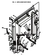
Страница 27: ...23 FIG 2 EXPLODED PARTS VIEW 43 43 1 37A 37B 43 43 1 37A 37B...

Страница 28: ...ch 43 1 2 75 Drop In Height Adapters 4 14 Switch 1 44 Cable 2 15 Nut 4 45 Haxangular nut 4 16 Safty cable 1 46 Spring board 8 17 Column parts 2 47 bronze spindle 6 18 Safty board 1 48 Idler wheel 6 19...

Страница 29: ...25 FIG 3 ELECTRICAL POWER SUPPLY KM POWER SUPPLY 0 M CONTACTOR CONTACTOR...

Страница 30: ...fitting 1 3 Annectent spindle 1 4 Check valve 1 5 Lowering valve 1 6 Bolt 1 7 Throttle valve 1 8 Escape oil valve 1 9 Oil box 1 10 Suction oil hose 1 11 Gear pump 1 12 Bumper valve 1 13 Valve seat 1...

Страница 31: ...27 FIG 5 DIMENSIONS 38 58 3 4 32 1 2 48 1 2 108 145 144 3 4 min 5 max 72 117 3 8 17...

Страница 32: ...items such as but not limited to rubber wheel vise pads Titan Bulldog Moto Cradle Wheel Chock is warrantied for replacement parts only to the original purchaser for a period of 2 years from the date...

Страница 33: ...Titan Lifts product you must register your product with us The simplest way to do this is to visit TITANLIFTS COM WARRANTIES and submit your information online If you prefer to send your information...

Страница 34: ......

Страница 35: ...NOTES...

Страница 36: ...46142 1 888 908 4826 FAX 317 215 2770 www titanlifts com TITAN MARKETING LLC Copyright 2020 by Titan Marketing LLC All rights reserved No portion of this manual or any artwork contained herein may be...

Отзывы: