


14
1.
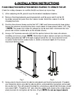
Before driving a vehicle onto the lift make sure the lift is fully lowered. Before driving a
vehicle onto the lift, position the lift arms outward. Do not hit or run over the lifting arms,
as this could damage the vehicle and/or lift. Make sure the lift is fully lowered before
moving the vehicle over the lift.
NOTE:
It is recommended to swing both arms outward
pointing toward the front of the lift prior to loading a vehicle onto the 10000AC-D.
2.
Drive the vehicle over the lift while keeping the vehicle parallel with the lift and aligning
the center of gravity of the vehicle with the center of the lift.
NOTE:
The “Center of
Gravity” (COG) of the vehicle is the balance point at which there is equal weight in front
of and behind the COG, and equal weight on both sides of the COG. The COG is not
necessarily the dimensional center of the vehicle, but is often slightly toward the engine
from the dimensional center of the vehicle.
3.
Turn off the vehicle’s engine and engage the parking brake of the vehicle.
4.
Read the vehicles owner’s manual to identify the recommended vehicle lifting points.
5.
Prepare the work area according to this manual. Move the lifting arms inward, and
position the rubber pads to contact with the vehicle manufacturer’s recommended
lifting points.
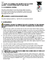
Press the power button to raise the carriages high enough up
off the locks so that they can be disengaged. Press down on the
lock release lever located on the power unit column to manually
disengage the both locks.
WARNING: ALWAYS RELEASE BOTH SIDES.
Press the lowering handle Fig. 1 until the lift is completely lowered.
7.3 OPERATION
NOTE: IT IS NORMAL FOR AN EMPTY LIFT TO LOWER
SLOWLY - IT MAY BE NECESSARY TO ADD WEIGHT.
7.2.3 LOWERING CONTROL
Fig. 1
WARNING: FAILURE TO OPERATE THE LIFT ACCORDING TO THIS MANUAL
MAY CAUSE DAMAGE TO THE LIFT, PROPERTY DAMAGE AND/OR PERSONAL
INJURY.
IMPORTANT: PLACE THE FOUR RUBBER PADS UNDER EDGE OF VEHICLE AT
THE FOUR JACK POINTS.
6.
Once the lifting arms have been positioned under the vehicle lifting points, operate the
power switch to make contact and lift the vehicle slightly. Test to make sure the vehicle
is well balanced and the contact between the rubber pads and vehicle lifting points are
secure by performing the “BUMPER TEST.” (pg. 2) Then proceed to lift the vehicle to the
desired height.
Содержание HD2P-10000AC-D
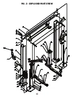
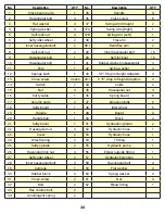
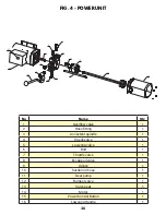
Страница 27: ...23 FIG 2 EXPLODED PARTS VIEW 43 43 1 37A 37B 43 43 1 37A 37B...
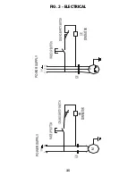
Страница 29: ...25 FIG 3 ELECTRICAL POWER SUPPLY KM POWER SUPPLY 0 M CONTACTOR CONTACTOR...
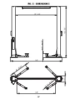
Страница 31: ...27 FIG 5 DIMENSIONS 38 58 3 4 32 1 2 48 1 2 108 145 144 3 4 min 5 max 72 117 3 8 17...
Страница 34: ......
Страница 35: ...NOTES...