background image

OPERATING INSTRUCTIONS

11

BEFORE USING THE CHIPPER

IT IS ESSENTIAL TO CARRY OUT THE FOLLOWING TESTS

to check safety equipment - this

sequence of tests will only take a few seconds to carry out.  We recommend that these tests are 
carried out daily. Observing the function as described will confirm that the safety circuits are working
correctly.  This is also a good opportunity to remind all operators of the control and emergency stop
systems.

4

7

5

6

8

2

3

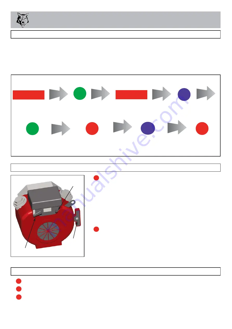
PRESS THE GREEN

BUTTON  

THE ROLLERS 

SHOULD RUN

PRESS THE RED BAR

THE ROLLERS

SHOULD STOP

PRESS THE BLUE BUTTON 

THE ROLLERS SHOULD TURN

BACKWARDS ONLY WHILE THE

BUTTON IS PRESSED

PRESS THE GREEN BUT-

TON AGAIN  

THE ROLLERS

SHOULD RUN

PRESS THE EMERGENCY

RED BUTTON  

THE ROLLERS

SHOULD STOP

PRESS THE BLUE BUT-

TON

THE ROLLERS

SHOULD NOT TURN

PULL TO RESET

THE RED BUTTON 

THE MACHINE IS

READY TO USE

1

PRESS THE RED

BAR TO POWER

THE CONTROL

SYSTEM

WITH THE ENGINE RUNNING AT FULL SPEED

STOPPING THE ENGINE

SET

engine to idle position.

ALLOW

to run for at least one full minute.

SWITCH 

off and remove ignition key.

For more detailed information refer to the  Engine Owner’s Manual

STARTING THE ENGINE

FOR A COLD ENGINE:

Place the throttle control at 1/3 throttle and pull the 
choke out.
Insert ignition key into starter switch.
Turn the key to start the engine.  Release the key as 
soon as the engine starts.
Gradually return the choke to the off position as the 
engine starts and warms up.  Allow the engine to warm 
up for at least one minute before chipping.

FOR A WARM ENGINE:

Follow the instructions for a ‘cold engine’ but return the 
choke to the off position as soon as the engine starts.

If engine fails to start after 10 seconds leave for 1 
minute and try again.

CHOKE

STARTER
SWITCH

THROTTLE LEVER

Содержание TW 125PH

Страница 1: ...re Starting 10 Before Using the Chipper 11 Starting the Engine 11 Stopping the Engine 11 Starting to Chip 12 Chipping 12 Blockages 12 SERVICE INSTRUCTIONS 13 Service Schedule 14 Engine Servicing 15 Sa...

Страница 2: ...are adequately trained for operating this machine especially with regard to safe working practices Timberwolf s policy of constantly improving their products may involve major or minor changes to the...

Страница 3: ...r hour 1600 mm DIMENSIONS 2270 mm 3165mm 2625mm with feed tray folded 1335 mm PURPOSE OF MACHINE TIMBERWOLF TW 125PH SPECIFICATION Engine type Honda v twin petrol Maximum power 14 9kW 20hp Cooling met...

Страница 4: ...PARTS LOCATOR 3 SAFETY BAR FEED TRAY FUNNEL ROLLER BOX COVER DISCHARGE BUCKET DISCHARGE TUBE SPARE WHEEL BELT GUARD ROTOR HOUSING DISCHARGE CLAMP NUTS LIGHT BOARD CONTROL BOX BATTERY BOX COVER ENGINE...

Страница 5: ...KAWAY CABLE BATTERY FAN SECTION x2 HYDRAULIC OIL TANK TOW HEAD CUTTER BLADE x2 ROTOR DRIVE PULLEY FUEL TANK HYDRAULIC PUMP HYDRAULIC PUMP BELT ADJUSTER ENGINE SHAFT BELT TENSION ADJUSTER ENGINE PULLEY...

Страница 6: ...spray and dust that can irritate the skin This may lead to respiratory problems or even cause serious poisoning Check the material to be chipped before you start Avoid confined spaces and use a facema...

Страница 7: ...ver the machine is to be left unattended ALWAYS check the machine is well supported and cannot move ALWAYS operate the chipper with the engine set to maximum speed when chipping ALWAYS check visually...

Страница 8: ...r protection at all times to prevent possible damage to hearing All persons within a 4 metre radius must also wear good quality ear protection 93 3 dB 95 2 dB 96 3 dB 96 6 dB R 4 metres Guaranteed Sou...

Страница 9: ...should snap into place on the ball hitch If it doesn t repeat previous 2 steps WIND jockey wheel up until fully retracted and the jockey wheel frame is seated in its notch on the stem The chipper weig...

Страница 10: ...again by pressing either the GREEN FEED or BLUE REVERSE control buttons RED SAFETY BAR TEST To ensure the safety bar is always operational it must be activated once before each work session The roller...

Страница 11: ...hare the machine is ready to chip When the machine is not in use for short periods of time move the lever to the idle position tortoise or turn off completely FAST SLOW O 1 OFF ON START PETROL TANK IN...

Страница 12: ...LERS SHOULD NOT TURN PULL TO RESET THE RED BUTTON THE MACHINE IS READY TO USE 1 PRESS THE RED BAR TO POWER THE CONTROL SYSTEM WITH THE ENGINE RUNNING AT FULL SPEED STOPPING THE ENGINE SET engine to id...

Страница 13: ...hands There are sharp blades and any small movement of the rotor may cause serious injury CHECK that the chipper is running smoothly RELEASE the catches on the feed tray and lower Pull to release the...

Страница 14: ...TS OF TOTAL SERVICE AND MAINTENANCE OF TIMBERWOLF WOOD CHIPPERS YOU ARE STRONGLY ADVISED TO TAKE YOUR CHIPPER TO AN AUTHORISED AGENT FOR ALL BUT THE MOST ROUTINE MAINTENANCE AND CHECKS TIMBERWOLF ACCE...

Страница 15: ...e electrical wiring Replace hydraulic oil filter every year or 100 hours after service or repair work to the hydraulic system Replace hydraulic oil Axle maintenance Tow head maintenance Daily Check 25...

Страница 16: ...nd then the positive lead 3 Clean charge and or top up the battery as required 4 Refitting is the reverse of removal Apply a smear of petroleum jelly to the terminals to prevent corrosion The Timberwo...

Страница 17: ...transport Never dispose of old batteries in household waste BATTERY SAFETY INFORMATION Product name Copper Ease Copper Ease contains no hazardous ingredients at or above regulatory disclosure limits...

Страница 18: ...lead of the negative terminal first Ensure good ventilation Use suitable direct current chargers only Connect the positive terminal of the battery to the positive output of the charger Connect the neg...

Страница 19: ...place any damaged screws with new and coat each screw with copperslip over the whole of the thread 12 Retighten each screw to 60Nm 45lbs ft NOTE This torque setting is vitally important to ensure your...

Страница 20: ...uts on the under side of the chassis and slacken using a 19 mm socket spanner 3 Adjust the M8 bolt on the outside plate until the desired tension is achieved For instructions on checking belt tension...

Страница 21: ...se with a brush to each slide on roller box and on inner cheeks of slider DO NOT USE GRAPHITE BASED GREASE 7 NOTE Rollerbox slide weighs in excess of 20kg Remove wedge lower roller box slide and repla...

Страница 22: ...formance of the required maintenance listed in your Environmental Manufacturing LLP instruction manual In the event of a failure the Environmental Manufacturing LLP authorised Timberwolf dealer is to...

Страница 23: ...CERTIFICATE OF CONFORMITY 22...

Страница 24: ...IDENTIFICATION PLATE 23 EXAMPLE The identification plate is normally located on the nearside chassis beam close to the tow hitch see page 2...

Страница 25: ...YE LIFTING EYE TO BE INSPECTED EVERY 6 MONTHS OR BEFORE EACH USE ALWAYS VISUALLY INSPECT LIFTING EYE PRIOR TO EACH USE DO NOT USE LIFTING EYE IF DAMAGED ATTENTION CLEAN UNDER BLADES BEFORE REFITTING O...

Страница 26: ...TO REDUCE EXPOSURE TO NOISE DUST AND RISK FROM EJECTED PARTICLES DO NOT USE THIS MACHINE WITHOUT THE DISCHARGE UNIT FITTED FAILURE TO COMPLY MAY RESULT IN SERIOUS INJURY OR DAMAGE STOP ENGINE AND REMO...

Страница 27: ...ELECTRICAL DETAIL 26...

Страница 28: ...ACER BL O BLUE WITH ORANGE TRACER O BL BL R Part No 1406 Part No 1407 SPLIT TO SAFETY SWITCH N O N C N C N C N O N O N C INDUCTIVE SPD SIGNAL ENGINE BL R BL R RELAY FWD 86 30 87a 85 87 RELAY SAFETY 86...

Страница 29: ...HYDRAULIC LAYOUT 28 HY323 MOTOR MOTOR PUMP TANK HY1422 HY1423 HY1421 HY2750 HY1420 FILTER DCV...

Страница 30: ...blank...

Страница 31: ...L LAYOUT 36 ENGINE 37 FUNNEL 38 HYDRAULICS 39 ROLLER BOX 40 ROTOR 41 ROTOR HOUSING 42 V BELT TENSIONING TABLE 43 The following illustrations are for parts identification only The removal or fitting of...

Страница 32: ...avy Washer 1 3 0491 Bearing 6205 2 4 0411M Pulley 1 5 0472M Pulley Boss 1 6 N A to purchase Slider 1 7 0469MS Slider Block 1 8 1342PS End Plate 1 9 made in production Washer 1 10 0476 Plain M8 Nut 1 1...

Страница 33: ...uard Support 2 25 17505 Axle 1 26 1374 Fuel Tank Cap 1 27 18962PB Prop Support 1 28 0360 M10 25 Bolt 8 29 0839 M10 C Washer 28 30 0709 M6 C Washer 11 31 0712 M8 C Washer 14 32 0431 M12 40 Bolt 4 33 07...

Страница 34: ...Mount 2 11 2804 Bush M10 Top Hat 4 12 2807 AV Mount 20 x 16 2 Item Part No Part Name Q ty 13 0857 M5 A Washer 2 14 18103 M5 8 Pan Pozi 2 15 18168 M4 35 Pan Pozi 4 16 1348 Limit Switch 2 17 18100 M4 Wa...

Страница 35: ...quare 1 6 0430 M12 35 Cup Square 1 7 0134 Black Handle Grip 1 8 1649MS Discharge Clamp Handle 1 9 4109M M16 Clamp Nut 1 10 4131 Roll Pin 1 11 0434 M16 70 Hex Bolt 1 12 1354 M16 C Washer 1 13 2837M Cla...

Страница 36: ...ey 200 X 3 SPA 1 7 0310 Belt 1060 3 8 0983MS Pulley 139 X 1 SPA 1 Item Part No Part Name Q ty 9 1028S Trigger 1 10 0709 M6 C Washer 3 11 1236 M6 20 Bolt 3 12 4344 M10 30 Washer 1 13 0408 Bush 2012 1 1...

Страница 37: ...m 1 2 1407 Control Box Loom 1 3 1638 No Stress Sensor 1 4 3063 VE Battery Cable 1 5 3064 VEBattery Cable 1 Item Part No Part Name Q ty 6 17398 No Stress Loom 1 7 1401 Honda Adapter 1 8 0368 Battery 1...

Страница 38: ...t 2 6 0712 M8 C Washer 2 7 0839 M10 C Washer 8 8 1252 M10 50 Bolt 2 9 0277 M12 25 Bolt 2 Item Part No Part Name Q ty 10 4211F Muffler 1 11 supp d with engine M8 Nut 4 12 0702 M12 A Washer 2 13 1426 Oi...

Страница 39: ...Nylon Pistons 2 14 4342 M8 30 Csk Soc 1 15 4018S Pin Bracket 2 16 0712 M8 C Washer 8 17 1603 Die Springs 2 18 1605M Stainless Spacer 2 19 1599FR Bearing Washer 2 Item Part No Part Name Q ty 20 1570 S...

Страница 40: ...3 4295 3 8 Hose Bottom Motor to DCV 1 14 0211 3 8 BSP Plug 1 Item Part No Part Name Q ty 15 1703 Hydraulic Tank 1 16 1413 Tank Top Filter 1 17 0323 3 8 Hose Top Motor to Btm Motor 1 18 0766 3 4 3 4 BS...

Страница 41: ...o Part Name Q ty 26 0788 Plastic Bush 2 27 1362M Roller Body 2 28 0325M Roller Blade 12 29 0428 M12 30 Csk Soc 28 30 1361 Drive Spline 2 31 0386M M10 30 Cap Screw 5 32 18070 Roller Box Spring 2 33 029...

Страница 42: ...20 Thou Shim As Req d 8 0701 M10 A Washer 6 9 0900 M10 20 Star Cap Screw 6 Item Part No Part Name Q ty 10 083MH Cutter Blade 4 2 11 18275M Blade Pocket 2 12 0386 M10 30 Cap Screw 6 13 1571 Fan Section...

Страница 43: ...ver 1 16 0709 M6 C Washer 4 Item Part No Part Name Q ty 17 0348 M6 20 Pozi Pan 2 18 1416P Sensor Clamp 1 19 0438 M6 16 Pozi Pan 2 20 1410FO Inner Guard 1 21 18444FO Rotor Housing 1 22 0644 M12 P Nyloc...

Страница 44: ...EXTENDED BELT SPAN LENGTHS ON THE 250DH S425 S426 SHREDDER THE FORCE READINGS ARE INCREASED BY 0 5Kgf OVER THE DESIGN IQ OUTPUTS Force reading Kgf New belt Used belt TW MODEL No PUMP BELT Used belt Fo...

Отзывы: