


FUNCTION CHARACTERISTICS
59
NVA100X-D - Manual - 02 - 2016
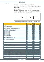
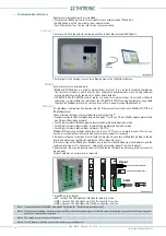
Fault trigger
When the programmed input is activated, a trigger is issued for fault record SFR). Data storing takes
place with the same procedure resulting from a trip of any protective elements.
Block2 IPh/IE
A change in status of a binary input effects a block
[1]
common for the following phase and ground
protective elements:
I
2
>,
I
2
>> (46M)
DthAL1,
DthAL2,
Dth
(49MG),
I
>,
I
>>,
I
>>> (50/51)
I
LR
>,
I
LR
>> (51LR)
I
-I/U
>,
I
-I/U
>> (51V)
and ground fault:
I
E1
>,
I
E1
>>,
I
E1
>>> (50N.1/51N.1)
I
E2
>,
I
E2
>>,
I
E2
>>> (50N.2/51N.2)
I
EC
>,
I
EC
>>,
I
EC
>>> (50NComp/51NComp)
I
ED
>,
I
ED
>>,
I
ED
>>> e
I
ED
>>>> (67N)
I
EDC
>,
I
EDC
>>,
I
EDC
>>>,
I
ED
>>>> (67NComp)
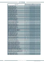
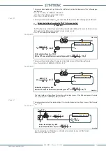
The application of the binary inputs for the acquisition of Block2 (selective block) coming from exter-
nal protection relays is shown in the following fi gure.
Block2 IPh
A change in status of a binary input effects a block
[2]
for the following phase protective elements:
I
2
>,
I
2
>> (46M),
DthAL1
,
DthAL2
,
Dth>
(49),
I
>,
I
>>,
I
>>> (50/51),
I
LR
>,
I
LR
>> (51LR),
I
-I/U
>,
I
-I/U
>> (51V).
Block2 IE
A change in status of a binary input effects a block
[1]
for the following earth protective elements:
I
E1
>,
I
E1
>> e
I
E1
>>> (50N.1/51N.1),
I
E2
>,
I
E2
>> e
I
E2
>>> (50N.2/51N.2)
I
ED
>,
I
EC
>,
I
EC
>> e
I
EC
>>>
(50NComp/51NComp),
I
ED
>>,
I
ED
>>>,
I
ED
>>>> (67N),
I
EDC
>,
I
EDC
>>,
I
EDC
>>> e
I
ED
>>>> (67NComp).
Block1
A change in status of a binary input effects a block for a length of time equal to the activation of the
input[3]; the element pickup that wish be blocked must be enabled (the
Block1
parameter must be
Note 1 The exhaustive treatment of the Block 2 function is described in the “Logic selectivity” paragraph.
Note 2 The exhaustive treatment of the Block 2 function is described in the “Logic selectivity” paragraph.
The application of the inputs for the acquisition of Block2 (selective block) for Phase (Block2 Iph) and earth protective functions (Block2 IE) is
similar to that illustrated in the scheme concerning the Block2 IphIIE
Note 3 Unlike the Block2 (selective block), that houses a safety logic founded on programmable timers, the Block1 (logic block) keeps block of the
protection for the whole time when the input is active.
•
•
•
•
•
•
•
•
•
•
•
•
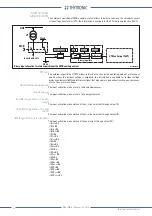
Trigger-faults.ai
Binary input allocation for fault recorder trigger
Fault trigger
T
0
INx
t
ON
T
0
n.o.
n.c.
INx t O N
Logic
INx t O F F
INx
t
OFF
Binary input INx
Fault recording
Protection
element
I
L1
->
I
L1r
I
L2
->
I
L2r
.....
DTheta->DTheta-r
Inputs
Outputs
Fault cause info
≥
1
Trigger-faults.ai
Binary input allocation for fault recorder trigger
Fault trigger
T
0
INx
t
ON
T
0
n.o.
n.c.
INx t O N
Logic
INx t O F F
INx
t
OFF
Binary input INx
Fault recording
Protection
element
I
L1
->
I
L1r
I
L2
->
I
L2r
.....
DTheta->DTheta-r
Inputs
Outputs
Fault cause info
≥
1
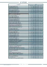
Binary input allocation for logic selectivity (Block2)
≥
1
≥
1
≥
1
Block2IPh/IE
T
0
t
B-Iph
BlockIph-Ie.ai
t
B-Iph
t
B-IE
xxxxx Trip Block2
Block2 input enable (ON
≡
Enable)
&
Block2 IN
towards reset timer
IPh Block2 input
IE Block2 input
Block2 IN diagnostic
Block2 input
FROM ANY PROTECTIONS
T
0
t
B-IE
IPh/IE Block2
Binary input INx
T
0
Logic
IN2
t
ON
INx
t
ON
IN2
t
OFF
T
0
FROM OVERCURRENT PROTECTIONS
n.o.
n.c.
INx
t
OFF
FROM EARTH FAULT PROTECTIONS


