background image

18

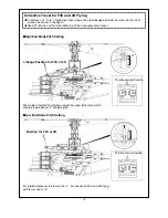
Move the throttle/collective stick to the full throttle position(see upper right diagram). The molded "pointer"

should now line up with the upper limit mark, which should provide about 12

û

of blade pitch.

Move the throttle/collective stick to the low stick position. Use the ATV function of your transmitter to make

the "pointer" line up with the 0

û

mark for beginners (with the -4

û

mark for intermediates, and -8-degree

mark for experts).

Throttle at High Position

Throttle at Low Position

n

High End Blade Pitch Setting

Low End Blade Pitch Setting

Linkage Position for beginner

n

Содержание RAPTOR 30

Страница 1: ......

Страница 2: ...E manual I did a very careful job in duplicating the manual but of course I can not assume responsibility in case of errors The duplicate has been kept as close as possible to the original manual but...

Страница 3: ...size helicopters The new PRO 39H R has much better transition characteristics than the Pro 36H ABC engine The needles are easy to set The ring design eliminates the criticalness of ABC engines You wil...

Страница 4: ...eceiver are turned on before starting the engine 7 The engine throttle must be in the idle position before starting the engine 8 Model helicopter main and tail rotors operate at high RPM Make sure not...

Страница 5: ...ocket Drivers Hex Wrench Grease Blue Locktite Instant Glue Hobby Knife Metric 4 way Wrench Scissors Nipper 5 5mm Wrench Needle Nose Pliers Screw Driver Glow Plug Wrench Gyro Glow Fuel 15 30 12V Batter...

Страница 6: ...tor kit are packed according to the assembly steps The part number and quantity contained in each are always shown in the square box on each page Do not open all the bags at once Open only the bag tha...

Страница 7: ...Fuel Tube 2 Note After assembly check to make sure the Fuel Tank clunk can move from top to bottom without touching the back of tank Also a fuel filter available from any hobby shop TTR1164 should be...

Страница 8: ...5B Set Screw M4x5 2 7 BK0081 Pin 2 8 BK0057 Servo Frame 1 9 BK0599 Main Frame Left Side 1 10 BK0600 Main Frame Right Side 1 11 BV0035 Guide Pulley 2 12 BK0036 Pulley Collar 4 13 BK0592 Starter Shaft 1...

Страница 9: ...BK0031 Main Spur Gear 1 5 BK0032 Tail Drive Pulley 1 6 BK0034 One Way Clutch Shaft 1 5 Washout Assembly 1 HMJ2 10N Self Tapping Screw M2x10 2 2 HMC3 10B Socket Screw M3x10 2 3 HMV740ZZ Bearing d4xD7x...

Страница 10: ...it 29BB version 7 will be replaced by Bushing BK0107x6 8 will be replaced by Bushing BK0108x2 Warning do not over torque the self tapping screws 1 HSE3 18B Self Tapping Screw M3x18 4 2 HSE3 12B Self T...

Страница 11: ...bly into position on the shaft and line up the holes in the main shaft with the holes in one way clutch shaft of the main gear assembly Insert the socket head screw and secure with the lock nut Next s...

Страница 12: ...lutch Shoe 1 3 BV0038 Cooling Fan 1 4 No 9604 TT PRO 39H R Engine 1 5 BK0170 Shim 1 1 HMC3 14B Socket Screw M3xH 8 2 HMC3 35B Socket Screw M3x32 2 3 BK0087 Flat Washer 4 4 BK0037 Engine Mount 1 5 No 9...

Страница 13: ...HMX0612 Thrust Bearing 2 12 HMV1360Z Bearing d6xD13xW5 4 13 BK0076 Collar 2 14 BK0078 Collar 2 15 BK0581 Flap Collar 2 16 BK0088 Flat Washer 2 17 BK0067 Flybar Paddle 2 18 BK0010 Flybar Rod 1 19 BK000...

Страница 14: ...ide linkage balls of the swash plate Assembly Tip Work from left to right when assembling the parts The tail pitch control lever screws into the arm extending from the tail unit housing For sport kit...

Страница 15: ...ert the tail rotor drive belt into the boom so that it comes out of both ends Place drive belt over tail drive pulley and complete balance of tail boom assembly Remember to connect the tail linkage ro...

Страница 16: ...the steel linkage balls Make sure all linkages are the correct length Before installing Aileron Servo tape the wire as shown 86mm 73mm Mount the Steel Linkage Balls at 10 5mm approx 7 16 from the cent...

Страница 17: ...embly Tip Remove all the servo wheels prior to attaching the steel linkage balls Make sure all linkages are the correct length On Off Switch Gyro Amplifier Receiver Battery Pack 2 BK0106 1 BE1052 Thun...

Страница 18: ...apping Screw M2x4 6 2 HSE3 12B Self Tapping Screw M3x12 2 3 BK0611 Body 1 4 BK0102 Rubber Grommet 2 5 BK0098 Body Clip A 1 6 BK0099 Body Clip B 1 7 BK0612 Canopy 1 8 JV0093 Decal 1 4 BK0102 4 BK0611 2...

Страница 19: ...t 6 To get the 0 to 12 collective range mount the steel linkage ball at 10 5mm away from the center of the collective servo horn 6 hovering pitch angle is used for beginners intermediates and experts...

Страница 20: ...12 of blade pitch Move the throttle collective stick to the low stick position Use the ATV function of your transmitter to make the pointer line up with the 0 mark for beginners with the 4 mark for in...

Страница 21: ...ttler to get the necessary servo travel The molded pointer should line up with the upper limit mark which should provide about 12 of blade pitch For intermediates set the low end to 4 For advanced F3C...

Страница 22: ...nly use the Normal mode values The model should hover at around 1550 rpm in Normal mode and flies at 1800 in idle up1 Rotorspeed can be checked using TTR2000 MTF 301 helicopter tachometer CONFIGURING...

Страница 23: ...hole should close completely Adjust the ATV function in your transmitter to achieve the above requirement Listen to the servo it should not make any binding noise Try keep the throttle ATV between 90...

Страница 24: ...22 FLIGHT TRAINING SECTION...

Страница 25: ...Adjustments Relationship between the control motion and radio transmitter Always check all the controls to make sure they move in the correct direction and there is no mechanical binding or noise fro...

Страница 26: ...just the engine Set the carburetor main needle according to the engine instruction Depending on the fuel and glow plug used the carburetor idle screw may require fine adjustment of 1 4 to 1 2 turn awa...

Страница 27: ...blades are in track it means the blade tips should follow the same path as they rotate 3 When both blades are in track the blade tips will appear to overlap as seen from the edge of the rotor plane If...

Страница 28: ...your helicopter 1 If the helicopter nose starts to yaw left or right then use the transmitter trim to compensate 3 If the helicopter noses down or up then yaw right yaw left A situation move to b B s...

Страница 29: ...ry difficult to control the model to prevent it from moving For a beginner it will also be difficult to determine whether the helicopter is in trim or not But with repeated practice close to the groun...

Страница 30: ...odel is hovering beyond one meter 3 feet altitude always descend slowly A panic drop can damage the helicopter 2 Always stand behind the model helicopter when learning how to hover Then you can watch...

Страница 31: ...exercise of translational flight 2 After a few hours of practicing step 1 and you are comfortable with translational movement start using some tail rotor control so the helicopter nose will point slig...

Страница 32: ...30 MAINTENANCE SECTION...

Страница 33: ...hen the transmitter throttle collective stick is at the center position 2 Does the engine throttle arm move properly The carburetor opening should be fully open when the transmitter throttle collectiv...

Страница 34: ...ged plastic part Do not repair broken rotor blades Always inspect the following items immediately Engine starting shaft All the gears Main shaft flybar and blade spindle Tail boom and support Vertical...

Страница 35: ...r clockwise 1 1 1 1 1 2 Changing the flybar 1 Loosen or remove the M3x10 set screws 2 Unscrew the control paddles Make sure the distance from the rotor shaft to both paddles are the same If the flybar...

Страница 36: ...move the tail rotor gear box from the tail boom 2 Take apart the blade grips and remove or loosen the M3x18 set screws 3 Remove the tail rotor hub 4 Pull out the tail rotor shaft 5 Remove the plastic...

Страница 37: ...re than 1700 RPM such as for aerobatics then it is recommended reinforcing the blade root section with epoxy The enclosed drawing illustrates how to remove the plastic blade grips and then carefully s...

Страница 38: ...36 PARTS LIST SECTION...

Страница 39: ...Seesaw AK0029 Main Shaft AK0031 Main Spur Gear PV0004 Mixing Lever PV0005 Flybar Control Rod AV0038 Cooling Fan Assy PV0002 Flybar Control Arm PV0012 Pitch Control Arm PV0015 Aileron Lever PV0017 Tail...

Страница 40: ...PV0033 Servo Frame PV0030 Tail Rotor Shaft PV0029 Tail Pulley Set PV0021 Guide Pulley Assy PV0038 Tail Fin PV0037 Tail Rotor Blade 38 PV0043 Tail Control Rod PV0039 Main Rotor Blades PV0036 Flybar Pad...

Страница 41: ...PV0060 Installation Set PV0058 Linkage Ball PV0057 Frame Spacer S Tail Rotor Grip PV0209 Washer Bag 39 PV0053 Rotor Bolt PV0049 Seesaw Brg PV0052 Tail Slider Brg PV0051 Lever Brg PV0062 Body Mount Rub...

Страница 42: ...PV0363 Fuel Tank PV0362 Main Frame Set PV0365 Thrust Brg 40 PV0268 Loctite 262 LOCTITE 262 GREASE PV0270 Grease For Bearing PV0267 Loctite 242 LOCTITE 242 GREASE PV0269 Grease For Plastic Gear PV0328...

Страница 43: ...5B M3X5 HMC3 10B M3X10 HMC3 12B M3X12 HMC3 14B M3X14 HMC3 20B M3X20 HMC3 25B M3X0 5L25 HMC3 32B M3X0 5XL32 HMC3 8B M3X8 HME3 10B M3X10 HME3 18B M3X18 HME4 5B M4X5 PV0088 Screw Bag 6pcs each PV0089 Sc...

Страница 44: ...07 Flybar Control Rod 2 11 PV0008 Flybar Rod BK0010 Flybar Rod 2 11 PV0011 Washout Set BK0014 Washout Base 1 5 BK0015 Flybar Control Lever 1 5 BK0016 Washout Linkage 2 5 BK0075 Link Ball 2 5 BK0077 Co...

Страница 45: ...4 HMC3 20B Socket Screw M3x20 1 15 HMM3Z Lock Nut M3 1 15 HMQ14 Retaining Ring 14 2 4 PV0021 Guide Pulley Assy BV0035 Guide Pulley 1 3 BK0036 Pulley Collar 2 3 BK0081 Pin D13xL18 1 3 PV0022 Engine Mo...

Страница 46: ...2 20 PV0056 Frame Spacer L BK0058 Frame Spacer L 5 3 PV0057 Frame Spacer S BK0059 Frame Spacer S 10 3 PV0058 Link Ball BK0075 Linkage Ball 12 13 PV0059 Tail Shaft Brg HMV1150 Bearing d5xD11xW5 2 13 PV...

Страница 47: ...Washer Bag BK0435 Washer d4xD11xt1 7 4 11 PV0210 Washer Bag BK0087 Washer d4xD8xt1 4 16 10 PV0223 Screw Bag HMC4 8B Socket Screw 20 11 PV0267 Loctite 242 1 PV0268 Loctite 262 1 PV0269 Thrust Bearing...

Страница 48: ...ing Screw 6 19 HSE3 12B Selftapping Screw M3x12 2 19 PV0365 Thrust Brg HMX0612 Thrust Bearing 2 11 PV0366 Decal JV0093 Decal 1 19 PV0367 Pinion Gear 9T BK0593 Drive Gear 1 2 PV0368 Clutch Liner BK0590...

Страница 49: ...Y PV0095 STABILIZER CONTROL ARM SET PV0098 AILERON L TYPE LEVER PV0102 HIGH PERFORMANCE MUFFLER 36 39 47 No 3830 Raptor 30 V2 to 50 V2 Conversion Kit No 3832 Raptor 30 to V2 Conversion Kit No 3831 Rap...

Страница 50: ...0338 METAL MAIN ROTOR HUB FOR V2 PV0390 R50 CARBON TAIL BOOM PV0394 CARBON FIBER LOOK CANOPY PV0321 REAR MOUNTED TAIL SERVO TRAY PV0356 60 DUROMETER FLAP DAMPER PV0382 80 DUROMETER FLAP DAMPER PV0380...

Отзывы: