GPX3800 and GPX3850 Glass Processors
Chapter 5: Operation
Page 30
TTN047534-D02
5.5.4. Active XY Alignment
The active alignment method should be used for fibers which have a high core eccentricity. In such a case, and
the edge alignment method cannot ensure proper alignment of fiber cores. Active alignment is a core-to-core
alignment which uses output from an optical power meter to maximize the power transmission.
Use active alignment after a basic align process has been completed. In active alignment, the fiber is first moved
away from the aligned position and then back towards the stationary fiber to eliminate motor backlash. At this
point, a reference power meter reading is taken. The fiber is then moved and another power meter reading is
taken and compared to the reference. This process continues until the power meter measurement reaches a
maximum. The fiber is then driven back to the maximum power meter reading position.
5.5.5. Core Alignment
The core alignment method is similar to the edge alignment method, except the system attempts to align the fiber
cores, rather than aligning the fiber edge. This process may only be used where there is a clearly visible image of
the core. It is also essential that the core image is not distorted by the cladding.
5.5.6. End View Alignment (or PM alignment)
The end view alignment method is used when splicing polarization-maintaining fibers such as elliptical-core fiber
(PM or PZ), panda-style PM fiber, bow-tie style PM fiber or a hybrid splice between any of these
.
These types of fiber require the cores to be rotationally aligned in addition to the standard XY alignment.
The end view alignment process is initiated by using the “Lens Left or Lens Right” process in the software GUI.
This process instructs the fibers to be pulled back so that the mirror tower can be inserted between two fiber end
faces. The image of the fiber end is then displayed for automatic alignment.
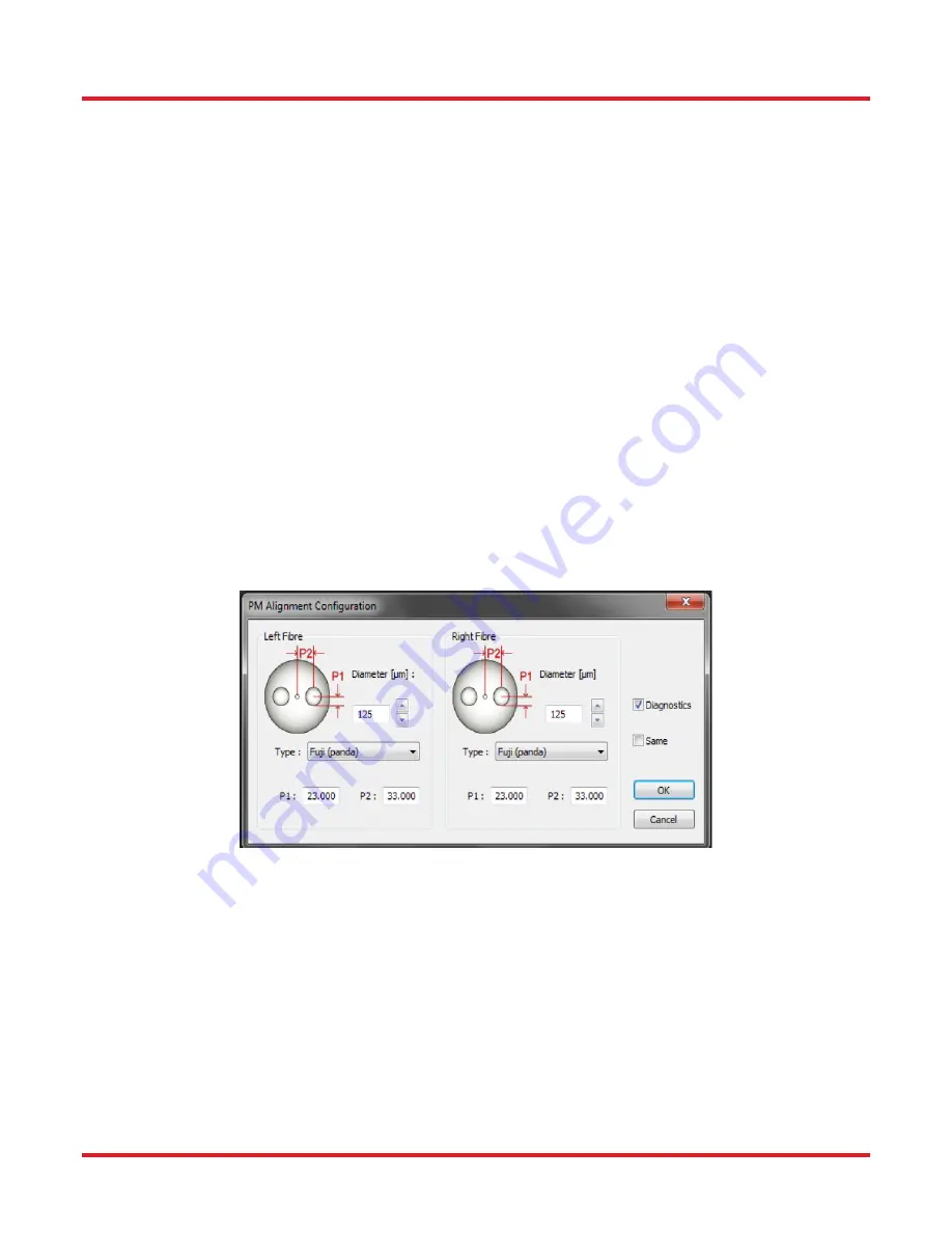
PM alignment settings
To begin the process, select the Alignment menu then select “Enable PM Alignment”. Select “PM,” and the PM
alignment window will be displayed. This window consists of 4 parameters for both the left and the right fiber.
Enter the fiber cladding diameter, fiber type and the two PM geometry parameters as indicated in Figure 11.
These values must be entered for both fibers; if the values are the same for both fibers, then check the “same”
window. If the operator does not know the exact characteristics, it is possible to directly measure them on screen.
Please note that the P1 and P2 values are measured in pixels.
Normally after the “Lens Left” process, a sequence such as, “Auto Exposure”, “End View Focus”, “Auto
Exposure”, “End View Process”, would be inserted to align the fiber. If the operator is unhappy with the alignment,
the process can be stopped and the fibers can be manually aligned.
Содержание vytran GPX3800
Страница 1: ...GPX3800 and GPX3850 Glass Processors User Guide ...
Страница 81: ...www thorlabs com ...


