background image

GPX3800 and GPX3850 Glass Processors 

Chapter 5: Operation 

Page 20


TTN047534-D02 

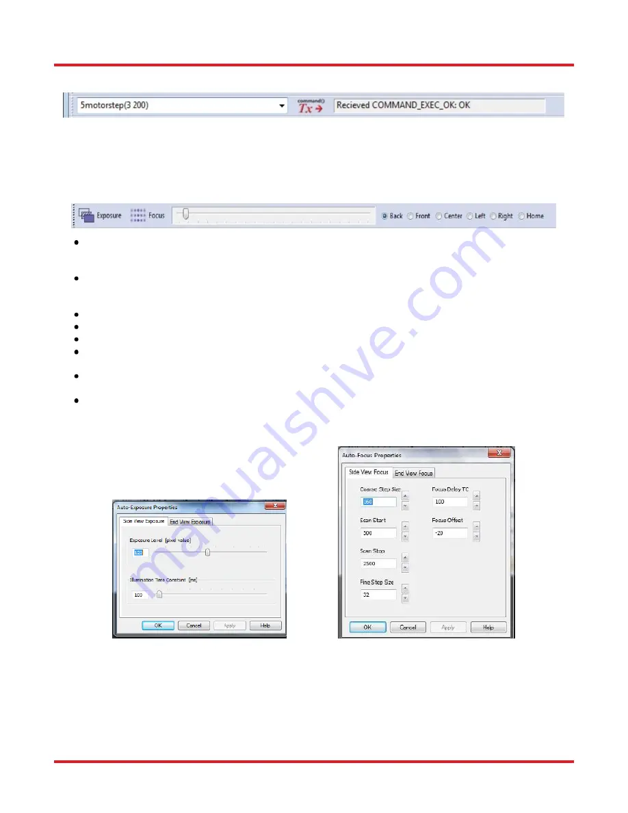
5.2.2. Command Bar 


The transmission and receive command bar allows the user to directly enter a command to perform motion 
control of the motors. In the example above, the motor 3 (lens position) is moved forward by 200 steps. 
Commands are entered into the white window. The window to the right of the “Tx” button shows the machine code 
response. 

5.2.3. Camera Bar 


  The “Exposure” button automatically adjusts the image so that the background is the desired brightness. 

To  change  the  brightness  setting,  right  click  the  button  and  click  “View  Properties.”  Then  change  the 
exposure values and illumination time constants as you see fit. 

  The “Focus” button automatically focuses the camera on the fiber. To change the properties of the auto-

focus  process,  right-click  the  button  and  click  “View  properties.”  Then  change  the  focus  parameters  as 
you see fit. 

  Next to the “Focus” button is a slider for manually adjusting the focus. 
  Next to the slider bar is a row of radio buttons for choosing the view position. 
  “Home” is the position for storage and when manipulating fibers. 
  “Back” and “Front” are two different side views used to align fibers. The Back view is usually used as the 

referenced view. 

  “Left” and “Right’ views show the fiber end face. External illumination may be necessary for certain fiber 

types. 

  In this document, and in the GUI, the word “process” is used to denote a machine action that has been 

programmed using low-level programming language, and therefore cannot be changed by the user. This 
is in contrast to a “macro,” (which can be changed or created) by the user. 


Auto-Exposure (Left) and Auto-Focus (Right) Properties Windows 


Содержание vytran GPX3800

Страница 1: ...GPX3800 and GPX3850 Glass Processors User Guide ...

Страница 2: ...d Bar 20 5 2 3 Camera Bar 20 5 2 4 Process Bar 21 5 2 5 Macro Bar 21 5 2 6 Quick Open File Bar 21 5 2 7 Main Toolbar 22 5 2 8 Splice Process List 23 5 2 9 Camera Image 23 5 2 10 Movement Control Bar 24 5 2 11 Status Bar 26 5 3 Initialization and Shutdown 26 5 4 Storage and Transportation 27 5 5 Fusion Splicing 27 5 5 1 Filament Fusion 27 5 5 2 Filament Normalization 29 5 5 3 Edge Alignment 29 5 5 ...

Страница 3: ...GPX Cleave Tension Base 51 6 1 8 GPX Cleave Backstop Adjust 52 6 1 9 GPX PreTension 52 6 1 10 Typical Process List for GPX Cleave 53 6 2 Hot View Imaging 53 6 3 End View Quality Tool 55 6 3 1 End View Quality Tool User Interface 55 6 3 2 Rectangle Tool 56 6 3 3 Circle Ellipse Tool 57 6 3 4 AutoLocate Tool 58 6 3 5 Centroid Tool 59 Chapter 7 Maintenence 60 7 1 General Care 60 7 2 Keep the System Cl...

Страница 4: ...erts 69 8 2 Bottom Inserts 69 8 3 Fiber Holder Insert Size Selection Guide 70 Chapter 9 Specifications 72 9 1 Electrical Power 73 9 2 Gas Supply 73 9 2 1 Gas Supply Specifications 74 Chapter 10 Regulatory 75 Chapter 11 Thorlabs Worldwide Contacts 76 ...

Страница 5: ... Symbol Description Direct Current Alternating Current Both Direct and Alternating Current Earth Ground Terminal Protective Conductor Terminal Frame or Chassis Terminal Equipotentiality On Supply Off Supply In Position of a Bi Stable Push Control Out Position of a Bi Stable Push Control Caution Risk of Electric Shock Caution Hot Surface Caution Risk of Danger Warning Laser Radiation Caution Spinni...

Страница 6: ...ment has been on for a few seconds such as after a splice or tapering operation WARNING The fiber handlers and the splice head can exert a fair amount of force as they move from side to side Do not put your fingers between them or between the fiber handlers and the slot end walls while the machine is in operation DANGER The camera tower on the glass processors can generate a fair amount of force a...

Страница 7: ...and convenient data storage This level of control combined with the consistency of filament fusion technology makes the glass processors a multipurpose platform for the production of fiber laser and other specialty fiber applications The Vytran Glass Processors consist of four different models designed to perform high quality fusion splicing and tapering of specialty fibers The system consists of ...

Страница 8: ...Item GPXFBT KITA Software and Fixture Kit with Removable Taper Holder Item GPXFBT KITB Mountable Gooseneck Light for GPX Glass Processors Item GPXL1 3 2 2 GPX3850 Standard Features Fiber Splicing and Tapering up to Ø1 7 mm Cladding Automated Splice Head XY Alignment Blocks with Rotary Capability Camera Tower with Ring Illuminator Liquid Cooling System Item GPXWCS Tension Monitoring and Control Sys...

Страница 9: ...7 Number 6 Also Included An Adaptor May be Required in other Areas or Countries Gas Line 1 8 PTFE Line for Argon Gas RS 232 Communication Cable 9 pin D sub Cable for RS 232 Communication Camera Cable 6 pin IEEE 1394 Fire Wire Cable Tool Kit Hex Wrenches for Filament and Inserts Replacement Fiber Holding Block Inserts Top and Bottom Inserts for Fiber Holding Blocks Filament Assemblies Set of Filame...

Страница 10: ...igure 2 GPX3800 Back Panel Connections Power The glass processor workstations are powered from an external dual voltage supply The GPX3800 uses a 5 pin round connector The GPX3850 utilizes a 2 pin 24 V and 3 pin 12 V power cord Communication PC GPX Control communication RS 232 9 pin D Sub connector Connect to Com 1 on the PC Camera PC IEEE 1394 6 pole connection Connect to IEEE 1394 on PC Analog O...

Страница 11: ...ric core fiber and for aligning surface features of non circular fiber GPX3800 and GPX3850 Fiber Holding Blocks The GPX3800 and GPX3850 fiber holding blocks can rotate each fiber up to 200 This is primarily used for aligning stress members of PM fibers but can also be used to align the cores of eccentric core fibers It can also be used to align surface features on fibers that are not round Rotary ...

Страница 12: ...ssor in the same insert that held them during cleaving and ensure that the ends of the fibers will fall exactly in the same place every time This is due to the fact that the transfer inserts are designed to precisely sit at the same location on both the cleaver and the glass processor and a magnetic lid on each transfer insert prevents axial movement of the fiber during transport from one piece of...

Страница 13: ...ment assembly please see Section 7 4 1 Changing the Filament Filament Tower Filaments The filaments are omega shaped resistive heaters Thorlabs offers these filaments preassembled in a variety of sizes as well as different materials that could be more appropriate to a particular splicing application Graphite filaments are capable of achieving the high temperature required for splicing large diamet...

Страница 14: ...hed by a version number engraved on the front of the housing Figure 6 V and T Filament Body Version Figure 7 lists the standard graphite filament types as a function of the fiber size and application Item Filament Material Application Cladding Diameter Min Max FTAV2 Graphite Splice 80 µm 250 µm FTAV4 125 µm 600 µm FTAV5 250 µm 1000 µm FTAV6 400 µm 1300 µm FTAT3 Tapering 250 µm 1500 µm FTAT4 400 µm...

Страница 15: ...wer moves in the X axis to provide the ability to view both the side view and end view of the fibers Mirror Tower 3 4 5 Imaging System The GPX3800 and GPX3850 workstations come with an automated camera assembly used for imaging the fibers This tower can be moved forwards and backwards as well as up and down It is equipped with a ring illuminator that provides backlighting for the front and back vi...

Страница 16: ...onnect the muffler to the top connector of the vacuum pump 5 Connect the bottom connector on the vacuum pump labeled VAC with the included tube to the back of the glass processor labeled VACUUM External Vacuum Pump 6 Connect the camera with the supplied IEEE 1394 Fire Wire cable to the port on the glass processor labeled CAMERA and to the Fire Wire port on the computer The connector has a directio...

Страница 17: ...en connect the gas line to the back of the glass processor to the port labeled ARGON 10 Connect the DC power cable to the back of the glass processor to the port labeled POWER with the ferrite end of the cable Plug the other end of the cable into the external DC power supply Note make sure to align the red dot on the plug with the red dot on the receptacle 11 Connect the AC power cord to the DC po...

Страница 18: ...tailed explanation for the control of the machine 5 2 Graphical User Interface The GUI is the main window when working on the glass processor workstation It has different menus and toolbars that are explained later in this document The buttons are described in this chapter from top to bottom as indicated in Figure 8 Figure 8 Software GUI Main Screen The following sections will explain each of thes...

Страница 19: ...preconfigured settings that should not be altered Engineer Mode Engineer mode allows full access of SW and control of the limited GUI for the Non Engineer Engineer Password Engineer mode is password protected Exit Close the GUI b View View enables the user to display or hide the various toolbars data windows and guides associated with the GUI like crosshair and alignment guides The Processes Toolb...

Страница 20: ...he machine parameters Four tool bars on the interface can be modified through Toolbars window Through the Edit Processes Bar the user can define which process will be shown in the user interface for quick usage Selected Processes window includes all the processes which will be shown on the screen Through the Edit Macro Bar the user can define which macro or commands will be shown on the screen ...

Страница 21: ...s for viewing the fiber Each camera position contains the settings for the camera and optics in that position In the CCD Camera property window the view settings allow the user to turn on and off all the cursors on the screen Camera settings are preset the user should not change these values Home to View Distance sets the distance between the splice home and the actual viewing position of the spli...

Страница 22: ... rates The purge and background settings are controlled in this window and argon flow rate for the splice is set in the splice property window The system can measure the cleave angle of the fibers before splicing them together The user can set the cleave angle limits to reject the poorly cleaved fiber The Filament Normalization values in this window are set by the manufacturer The process will be ...

Страница 23: ...ormation will be discussed in Section 5 5 1 e Reset The Reset Menu allows the user to initialize stop and reset the GPX window f Execute The Execute menu can be used to perform key splicing functions For descriptions of these functions see Illustrated Toolbar below g Help The Help menu provides information about using the GPX and the software and allows the user to save the event log ...

Страница 24: ... the camera on the fiber To change the properties of the auto focus process right click the button and click View properties Then change the focus parameters as you see fit Next to the Focus button is a slider for manually adjusting the focus Next to the slider bar is a row of radio buttons for choosing the view position Home is the position for storage and when manipulating fibers Back and Front ...

Страница 25: ...ord macro is used to denote machine actions that the user can edit or even create from scratch The macro bar can be edited using a right click on the empty space on the bar or clicking on the Configuration menu then clicking on Toolbars then clicking Edit Macro Bar The Command window will allow the user to add edit or delete the macro shown in the Macro Bar Note that it is possible to make buttons...

Страница 26: ...s in a perpendicular view The Alignment Process will not work if both edges of each fiber are not on the screen In the end view this process will rotate the fiber and align it based on the current PM Alignment Settings Core alignment This button aligns the cores of the fibers bringing the cores into alignment rather than aligning the fibers using their edges Active alignment This button aligns the...

Страница 27: ...lluminator Another way to get an edge view is to view the fiber pair straight on This is accomplished by clicking on Center View in the Camera Toolbar In this case the fiber will be backlit by an LED in the mirror tower Finally the unit is also capable of viewing fibers end on in Left or Right view This too is accomplished with mirrors on the mirror tower but in this case the illumination comes fr...

Страница 28: ...move an equal distance to maintain the relative distance and orientation between the two holding blocks The Left Block box enables the user to move the left fiber handler in and out The number shown is the position of the left block in microns and the positive direction is defined as in or towards the splice head Thus for the left block positive motion is to the right with 0 being the outmost posi...

Страница 29: ...The Right Pivot box enables the user to pivot the right fiber handler for alignment in the front view The Right Block box enables the user to move the right fiber handler in and out The number shown is the position of the right block in microns and the positive direction is defined as in or towards the splice head Thus for the right block positive motion is to the left with 0 being the outmost pos...

Страница 30: ...user has to do an automatic alignment This window indicates how much the fiber is rotated from horizontal horizontal being 0 This window indicates the splice loss This function not yet enabled This window is a cumulative on timer for the filament This window indicates the position of the cursor within the image window This window indicates the relative brightness of the pixel under the cursor when...

Страница 31: ... used to perform high quality fusion splices 5 5 1 Filament Fusion The glass processor uses a graphite or iridium filament to provide the heat necessary to fuse fibers together The filament is a resistive heater typically shaped like an upside down omega so that it is open at the top In the beginning of the process the fibers are roughly positioned in the center of the camera viewing area Dependin...

Страница 32: ...indow and enter the desired hot push in microns Push Velocity The is the velocity at which the hot push takes place in um sec Hot Push Delay This is the length of time the filament will heat up before the hot push is performed Check the hot push delay displayed in the Splice Menu To change the hot push delay select the hot push delay and enter the desired hot push delay in seconds A value of 200 m...

Страница 33: ...rget value the process will display a window message that the normalization has not converged and another attempt is needed In the event of a successful normalization regression values within 90 110 of the target value the system will display the message window saying normalization is successful and unit is ready for use To run a normalization process the user needs to prepare two cleaved fibers f...

Страница 34: ... The end view alignment method is used when splicing polarization maintaining fibers such as elliptical core fiber PM or PZ panda style PM fiber bow tie style PM fiber or a hybrid splice between any of these These types of fiber require the cores to be rotationally aligned in addition to the standard XY alignment The end view alignment process is initiated by using the Lens Left or Lens Right proc...

Страница 35: ...lculate the fiber end angle It is the fraction of the fiber diameter that contains the PM Structure 5 5 7 Multiple Stage and Multiple File Splicing For certain special applications the system can run several splice steps in a sequence The setup window can be accessed from Menu Bar Splice Splice Parameters Multiple Stage Splice Users can set up all the parameters for each splice step and add or rem...

Страница 36: ...iber holding blocks utilizing the transfer inserts described in Section 3 4 2 Fiber Holding Blocks Then press the Load Fibers button to bring the fibers into the correct viewing position While the transfer clamp insert hold a very accurate position using different cleave lengths will require different load positions To modify the load positions simply right click on the Load Fibers icon or Configu...

Страница 37: ...elliptical core fiber PM or PZ panda style PM fiber bow tie style PM fiber or a hybrid splice between any of these These polarization maintaining fibers are aligned rotationally and in the XY axes just as in the blind rotation algorithm The active rotation alignment method uses a polarization analyzer to precisely align the fibers rotationally A light source is connected to the end of one of the f...

Страница 38: ...in Figure 14 Figure 14 Image of Taper in Progress 5 7 4 Taper Properties The user can precisely define the taper created using the Taper Properties window which is shown below It is accessed by opening the Splice menu and then clicking on Taper Parameters The first tab in this window shown in Figure 15 lets the user determine the geometry of the taper The following are some brief notes regarding t...

Страница 39: ...age of reduction negative value or increase positive value in the filament power along the taper process The power varies from P at the beginning of the down taper to P Δ at the beginning of the waist and then varies back from P Δ at the end of the waist to P at the end of the up taper Filament Delay This is the amount of time the filament is on before beginning the tapering process Gas Flow Rate ...

Страница 40: ...t it will not crash into it during tapering So to avoid a crash you simply take the overall length of your taper and multiply by 1000 to determine the distance in micrometers that the right fiber holding block needs to move This is a very safe value because the right fiber holding block moves less than the total taper length The anti backlash mechanism compensates for any fiber holding block movem...

Страница 41: ...nd clicking on Zero in the Tension Monitor window Utilizing the Tension Monitor the user can pre load a tension to the fiber before the taper process and then use the feedback to modify the taper properties if needed As an example a standard 400 to 200 um taper should be pre tensioned to approximately 20 g This is typically done by moving the left fiber holding block to the left using the motor co...

Страница 42: ...s take place on the Filament Ramp tab of the splice properties and taper properties pages Access this page by clicking on the Splice menu Splice Menu Select Splice Properties or Taper Properties from the pull down menu Splice and Taper Properties Then Filament Ramp Tab Figure 19 Filament Ramp Settings The default setup is shown in Figure 19 ...

Страница 43: ...s started With furnace Up Down in the off position the filament will neither move to nor away from the processing position If the glass processor is fitted with an Iridium filament then Ramp Enable should be set in the off position If the glass processor system is fitted with a Graphite filament then Ramp Enable must be set in the on position to prevent damage to the graphite filament loop o When ...

Страница 44: ... 20 Editing Fire Polish Parameters in Preperation for Thermal Core Expansion 5 7 8 Fiber Lensing There are many different types of fiber lensing applications Some involve splicing a component onto the end of a fiber some involve altering the end of a fiber and some involve splicing a component onto the end of a fiber and then altering it using the furnace Users are advised to contact Thorlabs for ...

Страница 45: ...ll allow the user to fabricate smaller diameter symmetric tapers as well as 2x2 fused fiber couplers with high level of control of the process leading to very high repeatability of the process The GUI is separated into three tabs Global Properties In this window the user sets the global parameters as shown in the Figure 21 The parameters control the device type taper or coupler and the type of gra...

Страница 46: ...round its central position Reducing the furnace scan width will increase the rate of diameter change in the taper it will reach a smaller diameter with less elongation and less pulling distance Increasing the scan width will lower rate at which the diameter changes while creating a longer tapered region in the fiber In general the pull and scan velocities only affect the power required to fabricat...

Страница 47: ...sion Left and Tension Hold Right Interface Windows Tension Hold Process The tension hold process allows the user to apply and maintain a predefined tension value on the fiber or pair of fibers after a taper process has completed The process requires the user to input the target tension and tolerance in grams as well as the duration of the tension hold process The user needs to also specify which f...

Страница 48: ...ftware will stop the current stage after the specified period of time has elapsed 4 Disabled The software will not automatically end the current stage and the process will have to be stopped manually Furnace Scan Distance The furnace scan distance is the distance in mm that the furnace i e filament assembly will move around its zero position as defined by the Furnace Z Offset value The filament wi...

Страница 49: ...n required is estimated to be 12 0 mm 4 stages with an elongation of 3 0 mm each is one possible process Elongation is measured by the distance moved by one fiber holding block and therefore the actual total elongation is twice that value i e ElongAct ElongLeft ElongRight In general the first stage uses a constant filament power and maintains a constant tension on the fiber This will ensure that t...

Страница 50: ...s Cleave Blade to a Viewable Position GpxCleaveExposure Cleave View Exposure GpxCleaveFocus Cleave View Autofocus GpxCleaveHome Homes the Cleave Lever GpxCleaveBladeService Advances the Cleave Lever for Servicing GpxCleaveTensionBase Takes a Baseline Analog to Digital Converger ADC Reading for Tensioning GpxCleaveBackstopAdjust Provides a Visual Assist to Backstop Adjustment GpxPreTension Provides...

Страница 51: ...r is set to 80 steps Increasing this parameter and correspondingly the cleave forward steps parameter may be beneficial for the micrometer stop specialty process The cleave reverse steps parameter must always be less than the cleave forward steps parameter for the blade to oscillate toward the fiber Fiber Diameter The fiber diameter in micrometers Rotation Angle The rotation applied to the fiber i...

Страница 52: ...25 Figure 25 Auto Parameter Utility The auto parameter utility calculates a set of initial starting values for tension scribe delay and if making an angled cleave rotation angle Fiber Diameter The fiber diameter in micrometers Target Cleave Angle Desired cleave angle in degrees Distance Between Fiber Holding Blocks Distance in mm between fiber holding blocks Fiber Modulus Modulus of Rigidity in GP...

Страница 53: ...o 1 3 seconds This is enough time for the scribe to propagate and cleave the fiber if the scribe was too large Re Tension Pause seconds This parameter is the pause in seconds between each retension The optimal re tension pause is dependent upon the effective cross sectional area material properties and type of fiber as well as scribe size Experimentation will be required to optimize the re tension...

Страница 54: ...iew the cleave operation through the imaging system Figure 27 GPX Cleaver View Properties 6 1 3 GPX Cleave Exposure GpxCleaveExposure works in the same way as regular side view exposure This process provides the correct amount of illumination to be able to view the cleave process The GPX Cleave Exposure Properties window is identical to that of any regular side view exposure properties Figure 28 G...

Страница 55: ...sting or replacing the blade Machine Specific Blade Compensation steps A cleave blade position offset value that allows the user to compensate for small variations in the cleave blade fixing Ideally the data file from one GPX should be able to function correctly on another GPX This is achieved by maintaining the Cleave Blade Offset to a particular machine Cleave Counter Automatically increments af...

Страница 56: ... the backstop is adjusted the process window displays the measured deflection of each fiber The left and right vertical bars will show green if the fiber deflects towards the backstop and red when the backstop causes fiber deflection Figure 31 Cleave Backstop Adjust 6 1 9 GPX PreTension GpxPreTension is a newly developed process that allows the fiber to be placed under tension while the splice poi...

Страница 57: ...ing provides the ability to watch the splice or taper in real time through a special filter attached to the Ring Illuminator of the GPX Lens The Hot View Imaging is turned On via the Filament Ramp tab in the Splice properties menu Splice Splice Properties Filament Ramp The optical density filters are pivoted into place on the lens There are 2 filters of varying densities which can be used separate...

Страница 58: ...ower will not automatically go to the Home position before the splice The ideal position is for the lens to be in Center View thus looking directly down at the fibers during Hot View A prompt message is inserted into the Process List to instruct the user to put the filter in place and to remove the filter after the splice Figure 36 Hot View Process List and Prompt ...

Страница 59: ...d View Quality Tool Window The main window consists of a toolbar containing each of the measurement tools a scrollable viewing window and overlay information The measurement output is always rendered on the overlay Image magnification is increased or decreased by either resizing the window or by scrolling the scroll wheel of the mouse while the cursor is over the image Figure 38 Toolbar The toolba...

Страница 60: ...0 GPX3850 Page 56 TTN047534 D02 6 3 2 Rectangle Tool The Rectangle Tool allows the user to construct a bounding rectangle over the image The width height and diagonal measurements are displayed in microns in the overlay Figure 39 Rectangle Tool Button Figure 40 Rectangle Tool ...

Страница 61: ...le Ellipse Tool allows the user to construct a bounding circle or ellipse over the image The width and height measurements are displayed in microns in the overlay Figure 41 Circle Ellipse Tool Button Figure 42 Circle Ellipse Tool The Circle Ellipse Tool will also render the shape into the overlay giving an indication of the actual geometric shape ...

Страница 62: ...hapter 6 Added Capabilities of GPX3800 GPX3850 Page 58 TTN047534 D02 6 3 4 AutoLocate Tool The AutoLocate Tool automatically determines the diameter and position of a circular fiber Figure 43 AutoLocate Tool Button Figure 44 AutoLocate Tool ...

Страница 63: ...ies of GPX3800 GPX3850 Rev B July 24 2018 Page 59 6 3 5 Centroid Tool The centroid tool automatically determines the centroid of a fiber using the Center Of Area method This will work with any fiber geometry Figure 45 AutoLocate Tool Button Figure 46 Centroid Tool ...

Страница 64: ... the fiber ends and coating particles are cleaned off the workstation This type of debris can cause improper operation of the equipment 7 3 Fiber Handler Maintenance Fiber handlers must be cleaned periodically to ensure accurate fiber positioning It is also sometimes necessary to change inserts to accommodate different fiber sizes The following sections will discuss how these two tasks are accompl...

Страница 65: ...can be adjusted to accommodate fibers of slightly different diameter see Figure 48 for details To do this one must first loosen the two set screws in the back of the block One then adjusts the set screw in the bottom of the block If going to a smaller diameter fiber one turns the screw clockwise If going to a larger fiber one turns the screw counterclockwise The side of the block should remain flu...

Страница 66: ...the Lens Home macro button 3 Home the fiber holding blocks by clicking on FHB Home macro button 4 Switch the glass processor OFF 5 Remove the 2 screws that secure the stainless steel cover plates as seen in Figure 49 onto the furnace using a 5 64 hex key or balldriver Figure 49 Remove the screws on the stainless steel cover plates 6 Remove the Stainless Steel cover plates Figure 50 Remove the stai...

Страница 67: ...filament body and replace with a new one Be sure to have the filament V number inscription facing toward the front user side of the unit 9 Fit and secure the 2 screws that fasten the filament body to the furnace Do not over tighten use a Set the torque of 6 lb in Figure 52 Fit and resecure the filament body to the furnace 10 Refit the stainless steel cover plates and secure the two screws at a tor...

Страница 68: ...itioned in the center of the filament height wise ydirection If the Filament is too large to see the full filament housing on the screen use the command 5motorstep 3 XX to move the camera until you can see the filament housing edge Use the Filament XX and Filament XX to adjust the filament height Alternatively the motor step command on motor 14 can be used e g send 5motorstep 14 8 to raise the spl...

Страница 69: ...e lens assembly to the home position Move the fiber holding blocks to the home position View each mirror surface using a 10x eye loupe Item EYL10X Remove debris using a clean cotton swab and a commercial lens cleaner Please note that the mirrors are silver coated on the front surface Never use a cotton swab that has been laying on the work surface dust particles on a used cotton swab will scratch ...

Страница 70: ...ply place the cleave assembly onto the adapter plate in which the location is controlled by 2 locating pins The cleaver is secured by 3 screws The location of the 3 screws is shown by the red arrows below With the power of the GPX OFF plug the USB end into the socket CAUTION Do Not plug anything other than the GPX Cleaver into this USB socket ...

Страница 71: ... fiber and the fiber then moves sideways across the edge of the blade The most common occurrence of this is a result the cleave tension being set so low that the fiber is unable to be cleaved In this scenario the fiber will slide along the edge of the blade and take a small semi circular bite out of the current section For small localized damage such as this the blade can be re positioned up to a ...

Страница 72: ...e Initiate the purge using the Purge tool bar item Wait 5 10 seconds for the flow meter reading to stabilize Verify that the flow meter measures the set flow value Reset the purge flow rate to 2 l min on completion of the test Figure 56 Image of Argon Gas Port Left Flow Meter in Vertical Position Right 7 9 RMA Process Contact Thorlabs for information on requesting an RMA for a purchased GPX3800 or...

Страница 73: ...tible with the LFS4100 Fusion Splicer Fiber Holder Insert Side 1 Accepted Diameter Min Max Side 2 Accepted Diameter Min Max VHB00 57 µm 759 µm N A VHB05 410 µm 1008 µm 560 µm 1269 µm VHA00 57 µm 759 µm 275 µm 970 µm VHA05 410 µm 1008 µm 560 µm 1269 µm VHA10 812 µm 1515 µm 1036 µm 1770 µm VHA15 1288 µm 2022 µm 1534 µm 2268 µm VHA20 1772 µm 2505 µm 2032 µm 2944 µm VHA25 2278 µm 3029 µm N A VHA30 260...

Страница 74: ...ur chosen bottom insert Select a compatible top insert based on the fiber diameter size range shown in each cell Green cells indicate the best fit orange cells indicate the second best fit and white cells indicate the third best fit For the Ø800 µm example fiber from step 1 the green cell is in the 750 µm groove column for the VHA05 and VHB05 top inserts which have two grooves The numbers listed i...

Страница 75: ... 296 VHF750 750 µm 516 759 234 9 617 970 132 221 643 878 107 128 728 963 23 213 812 1047 62 297 VHE10 1000 µm 773 1008 172 63 858 1093 88 147 943 1178 3 232 1036 1271 90 325 1250 µm 1034 1269 176 59 1119 1354 91 144 1212 1447 2 237 1288 1523 78 313 VHE15 1500 µm 1280 1515 172 63 1373 1608 79 156 1449 1684 2 233 1534 1769 82 314 1750 µm 1534 1770 159 76 1611 1846 83 152 1695 1930 2 237 1772 2007 78...

Страница 76: ...ber End Viewing Facet Inspection and PM Core Alignment VHB00 or VHB05 Top Insert Required Core Cladding Fiber Diameter Automated Measurement End Face Inspection Inspection via GUI Display Cleave Angle Automated Measurement Fiber and End Face Alignment Fiber Z Axis Movement 180 mm Max Z Axis Movement Resolution 0 25 µm via Stepper Motor XY Axis Fiber Positioning Resolution 0 02 µm via Stepper Motor...

Страница 77: ...es with an external power supply unit which requires 90 260 VAC 47 63 Hz single phase This external power supply provides the unit with a 12 V line and a 48 V line 10 A max The glass processor workstation is controlled via a personal computer The computer serves as an interface between the user and the workstation The computer requires 115 or 230 VAC 47 63 Hz single phase 9 2 Gas Supply These glas...

Страница 78: ...er with specifications of 99 9995 purity with CO2 0 5 ppm H2O 0 5 ppm N2 3 0 ppm O2 1 0 ppm and THC 0 5 ppm When using a large tank of gas be sure the regulator is set to approximately 12 psi Do not exceed 25 psi under any circumstances If no gas pressure is present at the input port the splice station will interlock and the Low Argon message box will be displayed if operation of the filament is i...

Страница 79: ...to other Thorlabs products such as Pure OEM products that means assemblies to be built into a unit by the user e g OEM laser driver cards Components Mechanics and optics Left over parts of units disassembled by the user PCB s housings etc If you wish to return a Thorlabs unit for waste recovery please contact Thorlabs or your nearest dealer for further information Waste Treatment is Your Own Respo...

Страница 80: ...rmation USA Canada and South America Thorlabs Inc sales thorlabs com techsupport thorlabs com Europe Thorlabs GmbH europe thorlabs com France Thorlabs SAS sales fr thorlabs com Japan Thorlabs Japan Inc sales thorlabs jp UK and Ireland Thorlabs Ltd sales uk thorlabs com techsupport uk thorlabs com Scandinavia Thorlabs Sweden AB scandinavia thorlabs com Brazil Thorlabs Vendas de Fotônicos Ltda brasi...

Страница 81: ...www thorlabs com ...

Отзывы: