VoIP Business Phone Administrator Manual
Copyright © 2005 THOMSON
-All rights reserved
- Page 10
port of your PC to the PC port on the back of the IP phone using an Ethernet cable
(4) If you will be using a headset, plug the RJ9 headset connector into the headset
jack port on the left side of the IP phone. Remember to set the switch on the left
side of the IP Phone to the headset to disable the handset and enable the headset.
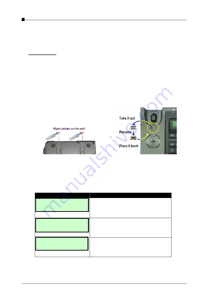
Wall Mounting
(1) Use the screws and wall plugs supplied as part of the wall-mount kit contained in the pack.
Drill the wall and secure the mounting screws at the correct spacing (please refer to the
mounting holes on the back of the IP phone).
(2) Mount the base (without handset) onto the screw heads.
(3) Remove the “Latch” from the on-hook handset position of the base (see below).
(4) Reverse it and replace it in its slot.
(5) Connect the Handset to the base unit and hang it in the on-hook position.
- Page 10 -
Correct wall-mounting positions
Figure 1.3 Mounting IP phone on the wall
1.4
Turning on the phone
When the IP phone is turned on, the system will boot up and the following information
will be displayed on the LCD screen.
LCD Screen
Description
Booting…
ST2020 Vx.y.z
When the system is initializing, all the settings
held in Flash memory are loaded and the
firmware version number is displayed (where
Vx.y.z is the current version number).
TEL: 1001
Mon May 10 08:24
Register Failed
Request Timeout
When the booting has been successful, the
LCD screen displays the phone number and
date/time.
If the booting fails after contacting the server,
the phone displays “Register failed: request
timeout”.
1.5
LCD Display
Содержание ST2020
Страница 1: ...Administrator Manual ...


