


Revision A
December 2011
11
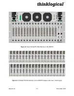
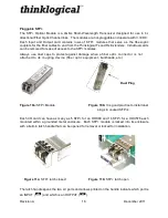
8 Position DIP Switch
(Located on the backplane on all HDX Router models)
HDX
Router DIP Switch Location & Settings
Back-up
Controller IP
Address
8 7 6 5 4 3 2 1
192.168.13.15
&
192.168.13.115
192.168.13.17
&
192.168.13.117
192.168.13.19
&
192.168.13.119
192.168.13.21
&
192.168.13.121
192.168.13.23
&
192.168.13.123
192.168.13.25
&
192.168.13.125
192.168.13.27
&
192.168.13.127
192.168.13.29
&
192.168.13.129
192.168.13.31
&
192.168.13.131
192.168.13.33
&
192.168.13.133
192.168.13.35
&
192.168.13.135
192.168.13.37
&
192.168.13.137
192.168.13.39
&
192.168.13.139
192.168.13.41
&
192.168.13.141
192.168.13.43
&
192.168.13.143
192.168.13.45
&
192.168.13.145
192.168.13.16
192.168.13.18
192.168.13.20
192.168.13.22
192.168.13.24
192.168.13.26
192.168.13.28
192.168.13.30
192.168.13.32
192.168.13.34
192.168.13.36
192.168.13.38
192.168.13.40
192.168.13.42
192.168.13.44
192.168.13.46
0 0 0 0 0 0 0 0
0 0 0 0 0 0 0 1
0 0 0 0 0 0 1 0
0 0 0 0 0 0 1 1
0 0 0 0 0 1 0 0
0 0 0 0 0 1 0 1
0 0 0 0 0 1 1 0
0 0 0 0 0 1 1 1
0 0 0 0 1 0 0 0
0 0 0 0 1 0 0 1
0 0 0 0 1 0 1 1
0 0 0 0 1 1 0 0
0 0 0 0 1 1 0 1
0 0 0 0 1 1 1 0
0 0 0 0 1 1 1 1
0 0 0 0 1 0 1 0
Primary Controller IP
Addresses
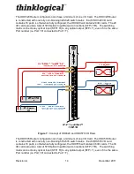
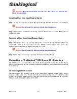
HDX
80 Router with front
cover removed
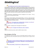
HDX
576 Router with
front cover removed
1
8
0
0
0
0
1
0
1
1
Pin 1 is on the bottom.
The left ← position = 1.
DIP Switch
Figure 5: HDX Router DIP Switch Locations and Setting
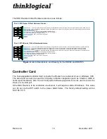
The simplest network connection is an isolated network with only the HDX Router, the control
server, and any control clients using static IP addresses. The HDX Router can be set to any of
the above settings. The control server must be at 192.168.13.9, and the control clients could
then be set to any other addresses in the 192.168.13.X family.
If static IP addresses for the control server and its clients are not possible, then the control
server will require two (2) network interfaces with one interface set to the static address
192.168.13.9 and dedicated to the HDX Router(s) while the other network interface can be
configured as required by the facility's network administrator.
A Back-Up Controller Card is optional to ensure uninterrupted functionality if the Primary
Controller Card should fail or need to be replaced. The Primary Controller Card should always
be in the left or upper controller slot. This card must have a LAN connection that allows it to
communicate with both the Primary Controller and a server having an IP address of
192.168.13.9. Without this interface the back-up controller will never take control of the router.
The server should have the firewall turned off or be configured so that it is able to respond to
pings from the Primary and back-up controllers.
Содержание HDX576
Страница 2: ......
Страница 8: ......
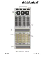
Страница 15: ...Revision A December 2011 7 Figure 2 HDX576 Router Rear View...
Страница 43: ...Revision A December 2011 35 Appendix B Quick Start Guides...
Страница 44: ...Revision A December 2011 36...
Страница 45: ...Revision A December 2011 37 Appendix C SD Flash Card Replacement...
Страница 46: ...Revision A December 2011 38...


