background image

- 20 -

Resistivity

Sensor

The controller displays and maintains resistivity between adjustable setpoints.
If the resistivity goes above the high setpoint, the line through the DI cartridge
closes. Flow through the DI cartridge resumes when the resistivity drops to the
low setpoint. If the resistivity drops below the low setpoint for more than one
hour, a fault is displayed, the REPLACE CARTRIDGE LED illuminates and a
remote signal is generated.

NOTE:

 Every time the controller is energized, a four hour clock disables the

REPLACE CARTRIDGE fault.

Devicenet

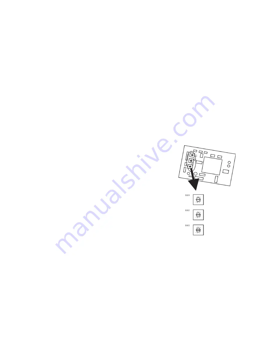
The Node Address and baud rate are all set with three rotary switches on the
devicenet board, see illustration below.

SW1 and SW2 are used to set the MAC ID. The MAC ID can be set from 1 to
63. It is factory set at 60. SW1 is the Most Significant Digit (MSD) and SW2 is
the Least Significant Digit (LSD). To set the device to a MAC ID of 60, set
SW1 to 6, SW2 to 0.

SW3 is used to set the baud rate. The baud
rate is factory set to 500K.

SW3 position

0 = 125K
1 = 250K
2 = 500K
3 = Blank

NOTE:

 If the baud rate is changed, recycle

the controller for it to read the change.

Содержание Neslab Dimax

Страница 1: ...t http www thermo com tc Product Service Information Applications Notes MSDS Forms e mail Voice Info 800 258 0830 NESLAB DIMAX DI Maximum Cooler Thermo Manual P N U00858 Rev 12 28 05 Installation Oper...

Страница 2: ...y materials from this manual in either machine readable form or any other form Sales Service and Customer Support 25 Nimble Hill Road Newington NH 03801 Tel 800 258 0830 Sales 8 00 am to 5 00 pm Servi...

Страница 3: ...FieldWiringRequirements 7 PlumbingRequirements 9 Fluids 10 FillingRequirements 10 MicroprocessorController 11 LEDs 11 Fault Messages 16 SECTION IV Operation Start Up 17 FlowTransducers 18 LowFluidLeve...

Страница 4: ...2 SECTION VI Service Troubleshooting Algae 26 Checklist 26 Service Assistance 27 SECTION VII Diagrams FlowDiagram 28 WiringDiagrams 29...

Страница 5: ...the unit is operated and found to be in good condition If the unit shows external or internal damage or does not operate properly contact the transportation company and file a damage claim Under ICC...

Страница 6: ...d in the reservoir Always turn off the unit and disconnect the line cord from the power source before performing any service or maintenance procedures Always empty the reservoir before moving the unit...

Страница 7: ...recirculation pump stainless steel reservoir built in replaceable deionizing cartridge and a microprocessor controller The controller monitors temperature controls resistivity and displays all fluid...

Страница 8: ...ange1 Pumping Capacity Facility Water Requirements Reservoir Volume Gallons Liters Unit Dimensions H x W x D Inches Centimeters 20 15 10 5 Pressure PSI 10 20 30 40 50 Flow rate gallons per minute 68 0...

Страница 9: ...supply and return should not exceed 65 psi Electrical Requirements Refer to the serial number label on the rear of the unit for the specific electrical requirements of your unit For high voltage 380 4...

Страница 10: ...psi at the mainframe Auxiliary supply 1 FPT Brass 25 psi max Facility water In Out 2 FPT Brass 100 psi max 50gpm max Higher pressures consult Thermo NESLAB Autorefill FPT Brass 75 psi max Unregulated...

Страница 11: ...manufacturer of the instrument should be able to recommend a cleaning fluid for their equipment The plumbing connections are located on the right side of the unit and are labelledFACILITYWATEROUT 2 F...

Страница 12: ...nit Do not use automobile anti freeze Commercial anti freeze contains silicates that can damage the pump seals Use of automobile anti freeze will void the manufacturer s warranty The selected fluid mu...

Страница 13: ...econds accelerates the changing value The display will flash as soon as either key is depressed and will continue to flash until the ENTER key is pressed to accept the new value The new value will not...

Страница 14: ...ys the temperature of the coolant leaving the chiller in C RESISTIVITY is the resistivity of the coolant leaving the chiller in meg ohms cm FACILITY WTR is the facility water flow rate in gallons per...

Страница 15: ...enu using the NEXT or LAST key press ENTER to go to the desired sub menu Scroll through the sub menu options using the NEXT or LAST key change the values using the YES or NO key Leave the sub menu usi...

Страница 16: ...and hold the ENTER key While holding the ENTER key enter the key sequence NO YES NO Scroll through the CONFIGURE menu using the NEXT or LAST key press ENTER to go to the desired sub menu Scroll throug...

Страница 17: ...ity out signal V Mohm the range of the temperature out signal 100mV C and the high and low flow calibration parameters Scroll through the CALIBRATE menu using the NEXT or LAST key press ENTER to go to...

Страница 18: ...on is depressed WARNINGLOWLEVEL Displayed when the tank level is less than 20 gallons The message clears after the fault is cleared and the RESET button is depressed HIGHTEMPERATURE Displayed when the...

Страница 19: ...lts prevent the pump from starting see Fault Messages on previous page For units with the GFI option be sure the GFI is in the ON position before closing the circuit breaker and turning on the unit De...

Страница 20: ...eset once the fault is cleared If the level drops below 16 gallons the alarm sounds and the pump is de energized Autorefill The unit has a nominal evaporation rate of up to 2 5 gallons per day Ensure...

Страница 21: ...n Pin 13 Low fluid level monitor output active if level is satisfactory sink current Pin 14 24VDC common output Common connection for flow switches and low fluid level safeties Pin 15 Flow monitor out...

Страница 22: ...ery time the controller is energized a four hour clock disables the REPLACECARTRIDGEfault Devicenet The Node Address and baud rate are all set with three rotary switches on the devicenet board see ill...

Страница 23: ...12 bits of resolu tion is available at the DeviceNet interface Facility Flow 0 to 10V range AI Digital Value Flow input to controller attheDeviceNetInterface 0 0 gpm 4095 100gpm ProcessFlow 0 to 10V...

Страница 24: ...LSB 15 Flow 6 MSB 16 Flow 7 LSB 17 Flow 7 MSB 18 Flow 8 LSB 19 Flow 8 MSB 20 Facility Water Flow LSB 21 Facility Water Flow MSB 22 AF WLW PUMP FW CB WLF 23 0 0 0 0 0 0 0 0 Upon receipt of a poll comm...

Страница 25: ...ndicates the status of the communication link Status LED Indication Notpowered Off Device not on line Noton line Device has not yet completed the Dup_MAC_IDtest Device may not be powered look at MODUL...

Страница 26: ...pable of communicating on the network Duplicate MAC ID or Bus off Communicationfaulted Flashing A specific communication faulted andreceivedan Red Green device Device has detected a identify comm faul...

Страница 27: ...e quick disconnects on the top and bottom of the cartridge and pull the cartridge from the unit Remove the hoses from both ends of the cartridge and then replace the cartridge When reinstalling ensure...

Страница 28: ...before closing the circuit breaker and turning on the unit Check fault messages Checkfluidlevelinreservoir Check power supply No poor controller display Open up the top panel and locate 1INST Turn th...

Страница 29: ...ly contact our Service Department Before calling please obtain the fol lowinginformation BOMNumber Serial number SoftwareVersion Application Type of fluid used Temperature at which the problem occurs...

Страница 30: ...28 Section VIII Diagrams Flow Diagram...

Отзывы: