


21
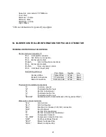
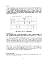
Speed vs. color code for *CTM Motor:
Low = Red
Med-Low = Purple
Medium = Blue
Med-High = Yellow
High = Black
*CTM is an abbreviation for Constant Torque Motor
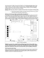
M. BLOWER CONTROLLER INFORMATION FOR PSC AND CTM MOTOR
TERMINAL DEFINITIONS & FIELD WIRING
Burner Harness Connector P1
Pin 1- Limit switch connector.
Pin 2- 120 VAC Line connection.
Pin 3- Burner pilot contact.
Pin 4&5-
120 VAC Neutral connections.
Pin 6- Burner pilot contact.
Pin 7&8-
From oil primary control.
Pin 9- Limit Switch Input (LSI).
Field Wiring to Burner
Harness Wires
Beckett Connections
Riello Connections
Thermostat / Humidistat connections
“C”
Common / ground
“W”
Thermostat call for heat
“R”
24 VAC to thermostat
“G”
Thermostat call for fan
“Y”
Thermostat call for cool
“DEHUM”
Humidistat call for dehumidification (TXV systems ONLY)
Male quick connect terminals.
“S1-3”
120 VAC Hot
“N1-7”
120 VAC Neutral
“EAC”
Electronic Air Cleaner (120 VAC) connection
“FAN”
Fan On Signal
“X”
24 VAC from transformer
“C”
24 VAC common from transformer
“CC”
Compressor Contactor
“CC_COM”
Compressor Contactor Common
“LOW”
Continuous Blower Speed
“HEAT”
Blower heat speed tap
“COOL”
Blower cool speed tap
Pilot (Tstat) Neutral Line
Yellow Wires
White
Red
T-T terminals
White
Black
T-stat terminals
White
Black
Содержание THV1M119A960SA
Страница 2: ......
Страница 4: ......
Страница 6: ...2...
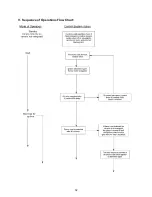
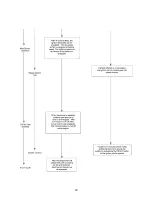
Страница 36: ...32 V Sequence of Operations Flow Chart...
Страница 37: ...33...
Страница 38: ...34 VI Trouble Shooting Flow Chart...
Страница 39: ...35...
Страница 40: ...36...
Страница 41: ...37...
Страница 42: ...38...
Страница 44: ...40 Appendix A Replacement Parts for THV1M119A...
Страница 45: ...41...
Страница 46: ...42 Appendix B THV1M119A960SA PSC Wiring Diagram...
Страница 47: ...43 THV1M119A9T5SA CTM Wiring Diagram...