16
I. OIL TANK AND PIPING:
: All local codes and ordinances take precedence with regard to selection and
installation of oil storage tank and oil supply (and return) lines. In the absence of local codes, all
tanks and lines must be selected and installed according to the instructions in this manual and
the Standard for the Installation of Oil-Burning Equipment, NFPA 31-1997, or the latest edition.
Burners are equipped with a single-stage, fuel pump. This type of fuel pump, when connected with a
supply line only, is satisfactory where the fuel supply is level with, or above the burner thus permitting
gravity flow of oil to the burner. If the tank is above the burner, and gravity oil feed to the burner is
permitted, a single line system may be used. The line should have a gradual slope downward of
approximately 1/2 inch per foot, or more, from the tank to a point directly below where it is connected to
the pump. Pitching the line upward toward the tank will help prevent the formation of air pockets in the
line.
NOTICE: An oil safety valve or a delayed-action, solenoid valve should be
installed in the oil supply line of all gravity-fed systems.
J. OIL FILTER:
It is strongly recommended that an oil filter assembly be installed in the oil supply line to the unit. This
filter should have the capacity to trap a 40-50 micron particle.
The filter cartridge should be replaced at least once a year. The filter body should be thoroughly cleaned
before installing a new cartridge.
K. ELECTRICAL WIRIING:
: This appliance must be grounded in accordance with local codes, or in the absence
of local codes, with the National Electrical Code, ANSI/NFPA 70-1999, or the latest edition.
All wiring must conform to the provisions of local codes or, in the absence of local codes, with the
provisions of the National Electrical Code, ANSI/NFPA 70-1999, or the latest edition, and this instruction
manual.
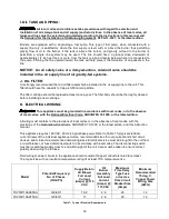
This appliance requires 120 VAC, 60 Hz, single-phase power. Refer to Table 7 for typical electrical
current draws of the individual appliance motors, recommended sizes for over-current and short circuit
devices, and minimum recommended field wiring sizes. Electrical service must be brought to the unit from
a circuit breaker, or fused disconnect switch, in accordance with local codes. The disconnecting switch
must be located reasonably close to and within sight of the unit. Care must be taken to ensure correct
polarity when wiring the furnace.
Field wiring of power circuits to the appliance should consist of copper conductors rated for at least
15 amp service with an insulation temperature rating of at least 75
C temperature rise.
Model
Potential/Frequency/
No. of Phases
(V/Hz/Ph)
Supply/Return
Air Blower
Full Load
Current
(Amps) @ 115
VAC
Oil
Burner
Assembly
Full Load
Current
(Amps) @
115 VAC
Maximum
Time Delay
Type Fuse
or Inverse
Time Circuit
Breaker Size
(Amps)
Minimum
Recommended
75 deg. C.
Copper Power
Wiring Size
(AWG)
THV1M119A960SA
120/60/1
19.2
2.6
20
12
THV1M119A9T5SA
120/60/1
11
2.6
20
12
Table 7: Typical Electrical Requirements
Содержание THV1M119A960SA
Страница 2: ......
Страница 4: ......
Страница 6: ...2...
Страница 36: ...32 V Sequence of Operations Flow Chart...
Страница 37: ...33...
Страница 38: ...34 VI Trouble Shooting Flow Chart...
Страница 39: ...35...
Страница 40: ...36...
Страница 41: ...37...
Страница 42: ...38...
Страница 44: ...40 Appendix A Replacement Parts for THV1M119A...
Страница 45: ...41...
Страница 46: ...42 Appendix B THV1M119A960SA PSC Wiring Diagram...
Страница 47: ...43 THV1M119A9T5SA CTM Wiring Diagram...

