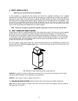
Thermo Products THV1M119A960SA Скачать руководство пользователя страница 14


 10 


B.  VENTING: 

NOTE:

 On the THV1M119A* it is possible to rotate the flue elbow (which is factory installed for vertical 

discharge) 90° counter clockwise or clockwise from the vertical position to adapt to various venting 
systems. 
 

Notice

:  Blocked Vent Switch Installation 

The blocked vent switch kit must be installed to comply with CAN STD B140.4 where applicable.  For 
installation instructions see RAOPS2687 kit. 
 

CAUTION MUST BE TAKEN NOT TO EXCEED 90°


ROTATION (OF THE FLUE 

ELBOW) .


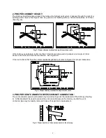
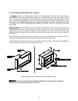
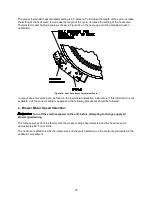
ROTATION OF FRONT FLUE ELBOW:


When an installation requires that the flue exit out the left or right side casing, remove the screw securing 
the 90 deg. elbow and rotate it 90°. Then, remove knock-out in side casing and extend vent through the 
opening.    
 
A trim collar may be ordered to hide the gap around the flue pipe. This trim collar, however, is not 
required for operation. Trim collar/gasket part numbers(s) R14132 / R330006 for THV1M119A*. 
 
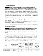
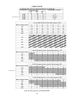
The THV1M119A* may be vented through a standard correctly sized chimney. 
 
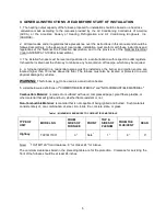
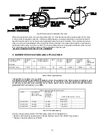
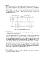
The THV1M119A* may also be horizontally vented through a sidewall. A field model FDVS-67/FOVP-615 
side wall vent kits for such applications is available. When installing the sidewall vent kits, outside 
combustion air must also be applied to the burner. The following table identifies application order 
information. 


Table 2:  Sidewall vent kits 


The Field vent kit is set up with a 6 inch diameter vent pipe for the THV1M119A* with concentric through-
the-wall vent termination/inlet air vent hood. For Beckett, the combustion air inlet pipe will be reduced to 
3” diameter with the Beckett sidewall vent kit. 
 
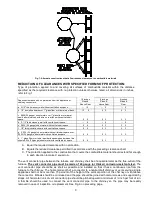
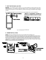
The side wall vent may be installed either through the knock-out on the right or left side casing of the unit 
or vertically out the top opening of the vestibule. 
 
The  combustion  air  inlet  can  be  installed  through  the  either  the  lower  left  side  casing  knockout  or  the 
lower right side casing knockout. 


FIELD VENT TERMINATION 

KIT

SIDE WALL VENT  

ACCESSORIES KIT

COMBUSTION AIR INTAKE 

HOOD KIT

(15’ application MAX)

(BURNER SPECIFIC)

(FOR COMBUSTION AIR 

APPLICATIONS ONLY)

PART NUMBER

PART NUMBER

PART NUMBER

     THV1M119A*

Beckett AFG

RAOPS8414

RAOPS8394

RAOPS8397

BURNER

SIDE WALL VENTING APPLICATION ORDER INFORMATION

Содержание THV1M119A960SA

Страница 1: ...AND LIQUIDS IN THE VICINITY OF THIS OR ANY OTHER APPLIANCE c WARNING IMPROPER INSTALLATION ADJUSTMENT ALTERATION SERVICE OR MAINTENANCE CAN CAUSE INJURY OR PROPERTY DAMAGE REFER TO THIS MANUAL FOR ASS...

Страница 2: ......

Страница 3: ...ANK AND PIPING 16 FILTER 16 J ELECTRICAL WIRIING 16 K BLOWER SETUP 18 L BLOWER CONTROLLER INFORMATION FOR PSC AND CTM MOTOR 21 M STARTUP PROCEDURES 26 III USERS INFORMATION SECTION 28 A OIL SUPPLY 28...

Страница 4: ......

Страница 5: ...Y A QUALIFIED SERVICE PERSON See Page 30 CAUTION DO NOT ATTEMPT TO MAKE REPAIRS YOURSELF See Page 28 WARNING The area around the furnace should be kept free and clear of combustible liquids and materi...

Страница 6: ...2...

Страница 7: ...r the Installation of Oil Burning Equipment NFPA 31 1997 or the latest edition and to these instructions The installation must also comply with CSA B139 for recommended installation practices where ap...

Страница 8: ...ow Requirements and Sizing of Ductwork section of this manual 5 Make sure supply and return air ducts are completely sealed to the appliance casing Refer to the Airflow Requirements and Sizing of Duct...

Страница 9: ...A furnace installed in a residential garage must be installed so the burner and ignition source are located higher than 18 inches above the floor The furnace must also be located or protected to avoid...

Страница 10: ...imney in a worse case situation Condensation most likely will not occur at the bottom of the chimney because the stack gas heats the chimney walls as it rises and the bottom will be heated first This...

Страница 11: ...feet above roof or exit point must be maintained See Figure 2b If the roof is flat rather than the normal residential pitched roof refer to Figure 3 for proper clearances Fig 3 Proper chimney terminat...

Страница 12: ...so they will seal to avoid air leaks 7 NO INTERCONNECTED CHIMNEY FLUES If chimney flues are divided or there are multiple flues within one chimney make sure there are no openings in the partition sepa...

Страница 13: ...ber or mineral wool batts sandwiched between two sheets 0 024 24 gauge sheet metal with ventilated air space 9 6 5 3 3 3 A Equal the required clearance with no protection B Equals the reduced clearanc...

Страница 14: ...may also be horizontally vented through a sidewall A field model FDVS 67 FOVP 615 side wall vent kits for such applications is available When installing the sidewall vent kits outside combustion air...

Страница 15: ...lel with or on the upstream side of the evaporator coil to avoid condensation in the furnace heat exchanger If the cooling unit is installed with a parallel flow arrangement dampers or other means use...

Страница 16: ...ilter rack can be held in position by tape or similar temporary means Position the open end of the filter rack so as to provide access for filter replacement Once the filter rack is positioned correct...

Страница 17: ...aximum Air Velocity ft min Model Number THV1M119A Supplied Permanent 600 480 in Standard Permanent 500 576 in Disposable 300 960 in Table 3 Minimum Required Filter Area in square inches The supplied f...

Страница 18: ...ber before installing burner The oil burner will mount on three stud mounting bolts on the lower mounting plate covering the opening in the front of the heat exchanger The end of the burner tube shoul...

Страница 19: ...EAD STATIC PLATE MAXIMUM NOZZLE SIZE SHIPPED NOZZLE SIZE OIL PUMP PRESSURE PSIG BECKETT AFG TP2701 N AFG 4 5 F6 2 3 4U 1 10X80 A 1 00X80 A 120 Table 5 Burner specifications INSULATOR S SLEEVE OR N NON...

Страница 20: ...y should be thoroughly cleaned before installing a new cartridge K ELECTRICAL WIRIING This appliance must be grounded in accordance with local codes or in the absence of local codes with the National...

Страница 21: ...tween EAC and N6 provides a switched 115 vac to power an electronic fan cleaner The same switched 115 vac is available between FAN and N7 and may be used in conjunction with a humidistat to control a...

Страница 22: ...his setting can be found in the thermostat installation instructions If this information is not available or if the correct setting is questioned the following procedures should be followed L Blower M...

Страница 23: ...87 971 9 38 923 9 01 895 8 68 864 8 23 829 High 13 5 1320 13 2 1290 12 8 1270 12 4 1240 11 3 1130 10 7 1090 10 2 1020 Speed Tap Static Pressure High Fire Temperature Rise vs External Static pressure i...

Страница 24: ...3 72 310 3 84 325 4 02 339 4 13 350 4 31 364 Med 3 74 314 3 91 327 4 11 345 4 25 360 4 39 374 4 60 390 4 74 406 MH 4 21 356 4 40 373 4 57 390 4 73 407 4 90 422 501 432 5 12 450 High 7 2 638 7 2 650 7...

Страница 25: ...arness Wires Beckett Connections Riello Connections Thermostat Humidistat connections C Common ground W Thermostat call for heat R 24 VAC to thermostat G Thermostat call for fan Y Thermostat call for...

Страница 26: ...will light when the control receives a call for dehumidification Refer to the Cool Mode section for the control operation Thermostat call for fan G 24 VAC thermostat input A call for fan is recognized...

Страница 27: ...ed from the thermostat If no other mode is calling for blower operation the control will operate the fan relay K4 and power the Low blower speed terminal The fan mode will be operated as long as the G...

Страница 28: ...tap only In the case of thermostat calls for Y and W together blower speed selection will be determined by the input that was first initiated In the case where the control is in a cooling mode with b...

Страница 29: ...nputs and are located directly below those inputs They will light to indicate the presence of these signals The red Board Status LED has two functions It will light when the board recognizes a valid i...

Страница 30: ...ed service technician or oil supplier To Turn Off Oil to Appliance i Set the thermostat to the lowest setting and set the operating mode switch to OFF ii If service is to be performed turn off the ele...

Страница 31: ...appliance heating section the following test instruments are required A smoke density measuring and rating device A carbon dioxide CO2 or oxygen O2 analyzer A flue gas temperature measuring device e g...

Страница 32: ...materials damage from rust or corrosion soot or carbon build up EXTERIOR OF FURNACE The furnace exterior should be inspected for signs of excessive heat such as discoloration of materials and damage...

Страница 33: ...removing any furnace access doors to service the air filters The air filters should be inspected each month and cleaned when dirty Cleaning the air filters frequently may reduce airborne contaminants...

Страница 34: ...eat exchanger will act as an insulator and reduce heat transfer resulting in less efficiency 1 To clean the heat exchanger first turn off all power to the unit Remove clean out plugs the vent connecto...

Страница 35: ...31 Figure 17 Heat Exchanger Clean Outs Vacuum Hose Length THV1M119A 8FT Fig 18 Recommended method and device for cleaning inside of heat exchanger...

Страница 36: ...32 V Sequence of Operations Flow Chart...

Страница 37: ...33...

Страница 38: ...34 VI Trouble Shooting Flow Chart...

Страница 39: ...35...

Страница 40: ...36...

Страница 41: ...37...

Страница 42: ...38...

Страница 43: ...FILTER DRAFT CONTROL COMBUSTION TESTS Operate burner at least 10 minutes before CO2 in stack pipe INITIAL SERVICE SERVICE SERVICE INSTALLATION Draft Over fire Draft in stack pipe Smoke number Furnace...

Страница 44: ...40 Appendix A Replacement Parts for THV1M119A...

Страница 45: ...41...

Страница 46: ...42 Appendix B THV1M119A960SA PSC Wiring Diagram...

Страница 47: ...43 THV1M119A9T5SA CTM Wiring Diagram...

Отзывы: