background image

45 

All installations and services must be performed by qualified service personnel. 


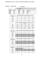
ALTERATIONS REQ’D FOR A/C @ DESIGN EXTERNAL STATIC PRESSURE


COOLING UNIT 


HTG Speed by Input 

Low                Mid             High 

Fire                Fire            Fire 

Recommended CLG Speed 


36,000 

LOW 

MED 

MH 

LOW 


42,000 

LOW 

MED 

MH 

MED LOW 


48,000 

LOW 

MED 

MH 

MED HIGH 

AS SHIPPED CLG. 


60,000 

LOW 

MED 

MH 

HIGH 


Speed Tap\ Static Pressure 

Furnace Airflow (CFM) vs. External Static pressure (in. WC.) 


0.1 

0.2 

0.3 

0.4 

0.5 

0.6 

0.7 


Low 

1454 

1392 

1321 

1255 

1158 

1074 

932 


ML 

1620 

1567 

1499 

1413 

1349 

1282 

1202 


Med 

1674 

1613 

1560 

1502 

1429 

1370 

1287 


MH 

1778 

1737 

1666 

1613 

1551 

1487 

1417 


High 

2148 

2091 

2029 

1973 

1928 

1884 

1834 


Furnace Motor Current Draw (Amps/Watts) vs. External Static pressure (in. WC.) 


Low 

3.4 

266 

3.6 

280 

3.7 

292 

3.9 

306 

4.0 

321 

4.2 

331 

4.3 

344 


ML 

4.4 

351 

4.6 

366 

4.7 

381 

4.9 

399 

5.1 

413 

5.2 

424 

5.3 

435 


Med 

4.9 

400 

5.1 

416 

5.3 

429 

5.4 

445 

5.6 

462 

5.8 

471 

5.9 

485 


MH 

5.8 

475 

5.9 

486 

6.1 

502 

6.2 

518 

6.5 

537 

6.6 

553 

6.8 

565 


High 

9.3 

806 

9.4 

815 

9.6 

837 

9.8 

855 

10.0 

874 

10.2 

891 

10.4 

912 


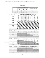
Speed Tap\ Static Pressure 

High Fire Temperature Rise vs. External Static pressure (in. WC.) 


0.1 

0.2 

0.3 

0.4 

0.5 

0.6 

0.7 


Low 

84 

88 

93 

98 

106 

114 

132 


ML 

76 

78 

82 

87 

91 

96 

102 


Med 

73 

76 

79 

82 

86 

90 

95 


MH 

69 

71 

74 

76 

79 

83 

87 


High 

57 

59 

61 

62 

64 

65 

67 


Speed Tap\ Static Pressure 

Mid Fire Temperature Rise vs. External Static pressure (in. WC.) 


0.1 

0.2 

0.3 

0.4 

0.5 

0.6 

0.7 


Low 

76 

79 

83 

88 

95 

103 

118 


ML 

68 

70 

73 

78 

82 

86 

92 

AS SHIPPED HTG. 


Med 

66 

68 

71 

73 

77 

80 

86 


MH 

62 

63 

66 

68 

71 

74 

78 


High 

51 

53 

54 

56 

57 

58 

60 


Speed Tap\ Static Pressure 

Low Fire Temperature Rise vs. External Static pressure (in. WC.) 


0.1 

0.2 

0.3 

0.4 

0.5 

0.6 

0.7 


Low 

64 

67 

71 

75 

81 

87 

101 


ML 

58 

60 

62 

66 

69 

73 

78 


Med 

56 

58 

60 

62 

66 

68 

73 


MH 

53 

54 

56 

58 

60 

63 

66 


High 

44 

45 

46 

47 

49 

50 

51 


OL8FA119T60 


Содержание OL6FA072D48B

Страница 1: ...ES MAT RIELS DES BLESSURES CORPORELLES OU DES PERTES DE VIE NE PAS ENTREPOSER NI UTILISER D ESSENCE OU AUTRES VAPEURS ET LIQUIDES INFLAMMABLES PROXIMIT DE CET APPAREIL OU DE TOUT AUTRE APPAREIL c AVER...

Страница 2: ......

Страница 3: ...that is not approved or is incompatible may result in personal injury substantial property damage or death cWARNING THE HEAT EXCHANGER MUST BE CLEANED BY A QUALIFIED SERVICE PERSON cCAUTION DO NOT ATT...

Страница 4: ...DRAFT REGULATORS 3 C DUCT WORK AIR CONDITIONING SUPPLY RETURN AIRFLOW AND AIR TEMPERATURE 5 D AIR FILTERS 6 E LIMIT POSITION 7 F BURNER INSTALLATION 7 G BURNER SPECIFICATIONS AND APPLICATIONS 9 H HEA...

Страница 5: ...ge must be installed so the burner and ignition source are located higher than 18 inches above the floor unless the required combustion air is taken from the exterior of the garage Also the furnace mu...

Страница 6: ...less of the efficiency of the design can perform satisfactorily when the chimney to which it is connected is inadequate or in poor condition Any of the following symptoms may indicate a chimney has se...

Страница 7: ...ace housing to allow the vent connector to pass through the housing If desired with the furnace flue elbow turned to the right the standard furnace top front panel p n 17346 2 may be replaced with the...

Страница 8: ...e cause of sooting Two 2 problems typically arise when power venting any oil fired appliance 1 Soot buildup may occur at an accelerated rate on critical components of the furnace oil burner e g the pr...

Страница 9: ...ature rise across the furnace in the range of 55 to 85 F Since the flow resistance of each duct system is slightly different the airflow fan speed may have to be changed in the field to achieve a sati...

Страница 10: ...ce and or void the warranty on this unit If a method other than internal Thermo Pride filter rack is selected for retention of the filters and or use of a different filter type is desired refer to Tab...

Страница 11: ...mounting bolts on the lower mounting plate covering the opening in the front of the heat exchanger The end of the burner tube should be inserted no further than 1 4 inch back from the inside surface o...

Страница 12: ...r amulet is provided on the burner tube of specific Thermo Pride burners see Fig 4 See Thermo Pride burner application chart for type of insulator Do not allow the burner tube or end cone to physicall...

Страница 13: ...A072D C 99032B N EZ 1HP 4 5 N A N A 0 75X60 A 0 60X60 A 120 OL8 A119T C 99032C N EZ 1HP 4 5 N A N A 0 90X60 A 0 85X60 A 140 Riello oil burner application FURNACE MODEL THERMO PRIDE S BURNER SPEC NO IN...

Страница 14: ...HR EFFECTIVE HEATING CAPACITY BTU HR Beckett Carlin Riello OL6 A060D 50 50 50 70 000 60 000 OL6 A072D 60 60 60 85 000 73 000 OL6 A090D 75 75 70 106 250 90 000 OL8 A101T 85 75 75 119 000 101 000 OL8 A1...

Страница 15: ...t exchanger will act as an insulator and reduce heat transfer resulting in less efficiency To clean the heat exchanger first turn off all power to the unit Remove clean out plugs the vent connector pi...

Страница 16: ...ONTROL BOARDS Thermo Pride oil furnaces can be equipped with one of the following two boards Please refer to Fig 7 to see which board you have Wiring Diagrams and Fan Speed Charts can be found in this...

Страница 17: ...e thermostat If the heat mode is not active or the anti short cycle delay is not in effect the control will energize the CC terminal and after a 10 second power demand conservation delay energizes the...

Страница 18: ...energized The control remains in steady heat mode until the thermostat is satisfied When the call for heat signal is removed the T T terminal is de energized and the blower off delay is started The o...

Страница 19: ...a Y call is initiated the blower speed will switch to the respective W or a Y speed following the blower on delay for that call The speed taps are interconnected and interlocked only one speed may be...

Страница 20: ...The fan mode will be operated as long as the G input is calling and neither the Heat mode nor the Cool mode is calling for blower operation When the Heat and Cool modes call for blower operation thei...

Страница 21: ...36 120 ON ON 48 240 OFF OFF 2 ON OFF 4 OFF ON 6 ON ON 8 Table 7 ON and OFF Blower Delay Time Switch Settings Motor Blower Speed Three interconnected blower speed outputs are provided A G call for fan...

Страница 22: ...ure use with a third party cloud based service called Aviexx Contact Aviexx com for more information Trouble Shooting Diagnostic Features for NRGmax board The control board is equipped with 1 Blue Boa...

Страница 23: ...ner compartment should be inspected by removing the front door of the furnace and looking for signs of excessive heat such as discoloration of components materials damage from rust or corrosion soot o...

Страница 24: ...combustion air adjustments Contact a qualified service person to adjust and start burner E Filter maintenance procedure Shut off the electrical power to the unit Open the blower access door Slide the...

Страница 25: ...21 All installations and services must be performed by qualified service personnel COMBUSTION AND EFFICIENCY TESTING FOR OIL FIRED CENTRAL FURNACES...

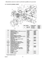
Страница 26: ...22 All installations and services must be performed by qualified service personnel Appendix A Replacement Parts Replacement Parts for OL6F 072D...

Страница 27: ...23 All installations and services must be performed by qualified service personnel...

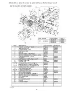
Страница 28: ...24 All installations and services must be performed by qualified service personnel Replacement Parts for OL6R 072D...

Страница 29: ...25 All installations and services must be performed by qualified service personnel...

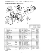
Страница 30: ...26 All installations and services must be performed by qualified service personnel Replacement Parts for OL8FA119T60...

Страница 31: ...27 All installations and services must be performed by qualified service personnel...

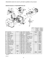
Страница 32: ...28 All installations and services must be performed by qualified service personnel Replacement Parts for OL8RA119T60...

Страница 33: ...29 All installations and services must be performed by qualified service personnel...

Страница 34: ...30 All installations and services must be performed by qualified service personnel...

Страница 35: ...31 All installations and services must be performed by qualified service personnel...

Страница 36: ...32 All installations and services must be performed by qualified service personnel...

Страница 37: ...33 All installations and services must be performed by qualified service personnel 57...

Страница 38: ...34 All installations and services must be performed by qualified service personnel...

Страница 39: ...35 All installations and services must be performed by qualified service personnel...

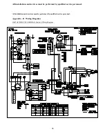
Страница 40: ...ns and services must be performed by qualified service personnel All installations and services must be performed by qualified service personnel Appendix B Wiring Diagrams OL6 A072D48 PSC NRGMAX Contr...

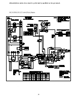
Страница 41: ...37 All installations and services must be performed by qualified service personnel OL6 A072DV5 ECM NRGMAX Control Wiring Diagram...

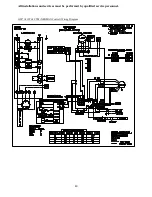
Страница 42: ...38 All installations and services must be performed by qualified service personnel OL6 A072D48 PSC UT Control Wiring Diagram...

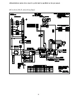
Страница 43: ...39 All installations and services must be performed by qualified service personnel OL6 A072DV5 ECM UT Control Wiring Diagram Note Refer to ECM Operation Manual supplied with furnace for ECM models...

Страница 44: ...40 All installations and services must be performed by qualified service personnel OL8 A119T60 CTM NRGMAX Control Wiring Diagram...

Страница 45: ...41 All installations and services must be performed by qualified service personnel OL8 A119T60 CTM UT control Wiring Diagram...

Страница 46: ...w 4 1 408 4 0 398 4 0 395 3 9 385 3 8 378 ML 5 3 540 5 3 535 5 2 527 5 1 512 4 9 500 MED 6 6 665 6 4 644 6 2 634 5 9 609 5 6 584 MH 7 6 772 7 2 739 6 9 713 6 6 682 6 4 663 High 9 6 951 84 830 9 0 887...

Страница 47: ...ting CFM Aprox Rise F 0 Aprox Rise F 0 Aprox Rise F 0 0 2 0 5 3 OFF 2 OFF 1 OFF 755 73 o 1 1 93 1 7 154 3 OFF 2 OFF 1 ON 826 66 o 80 o 1 2 105 1 9 168 3 OFF 2 ON 1 OFF 898 61 o 74 o 1 8 180 2 3 219 Fa...

Страница 48: ...SW 1 Switch Settings Clg Tonnage Cool Continuous 0 2 0 5 6 OFF 5 OFF 4 OFF 2 799 500 1 2 100 1 9 162 6 OFF 5 OFF 4 ON 2 5 1017 508 1 8 155 2 5 223 6 OFF 5 ON 4 OFF 3 1210 605 2 5 223 3 2 298 6 OFF 5...

Страница 49: ...4 6 366 4 7 381 4 9 399 5 1 413 5 2 424 5 3 435 Med 4 9 400 5 1 416 5 3 429 5 4 445 5 6 462 5 8 471 5 9 485 MH 5 8 475 5 9 486 6 1 502 6 2 518 6 5 537 6 6 553 6 8 565 High 9 3 806 9 4 815 9 6 837 9 8...

Страница 50: ...46 All installations and services must be performed by qualified service personnel OL8RA119T60...

Отзывы: