


18
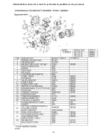
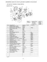
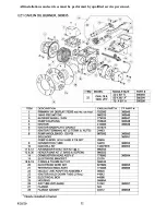
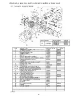
All installations and services must be performed by qualified service personnel.
The speed taps are interconnected and interlocked, only one speed may be powered at any one
time. When a speed is to be operated, the speed select relays are operated to select the path to the
motor tap and then the enable relay is operated to switch the operating power to the selected
motor speed tap. If the speed of the running motor is to be changed, first the enable relay
removes power from the motor, the new speed is selected and then power is restored to the
motor.
Blower On and Off Delays
Four Heat blower on and four blower off delays are selected by two dip switches for each
function. Refer to Table 7 for specific delay values.
Advanced Features
Tank Level, Refrigerant Temperature and Duct Sensor connections are for future use with a third
party cloud based service called Aviexx. Contact Aviexx.com for more information.
Trouble Shooting
-
Diagnostic Features for NRGmax board
The control board is equipped with 1 Blue Board Status LED, 6 Amber thermostat Input Status
LEDs, 3 Green Status LEDs and 3 Red Trouble Status LEDs. These are intended to provide a
quick view into furnace performance without requiring a voltmeter.
Normal LED Indicators
Thermostat Inputs: Amber LEDs indicate 24V signal present at terminal
Status: Blue LED pulses at various speeds to indicate operational state
24V Transformer: Green LED indicates that 24V transformer is powered
Blower: Green LED indicates Blower Relay is energized
Burner: Green LED indicates Burner TT Relay is energized
Trouble LED Indicators
Limit: Red LED indicates that High Limit is Open
Burner: Red Led indicates lockout alarm from Oil Burner (requires burner equipped with
Lockout Alarm Function)
24V O/L: Red LED indicates that an overload condition has caused the circuit protector to trip.
Содержание OL6FA072D48B
Страница 2: ......
Страница 27: ...23 All installations and services must be performed by qualified service personnel...
Страница 29: ...25 All installations and services must be performed by qualified service personnel...
Страница 31: ...27 All installations and services must be performed by qualified service personnel...
Страница 33: ...29 All installations and services must be performed by qualified service personnel...
Страница 34: ...30 All installations and services must be performed by qualified service personnel...
Страница 35: ...31 All installations and services must be performed by qualified service personnel...
Страница 36: ...32 All installations and services must be performed by qualified service personnel...
Страница 37: ...33 All installations and services must be performed by qualified service personnel 57...
Страница 38: ...34 All installations and services must be performed by qualified service personnel...
Страница 39: ...35 All installations and services must be performed by qualified service personnel...
Страница 50: ...46 All installations and services must be performed by qualified service personnel OL8RA119T60...