


ULTRA-CUT 400 XT
4-18
OPERATION
Manual 0-5275
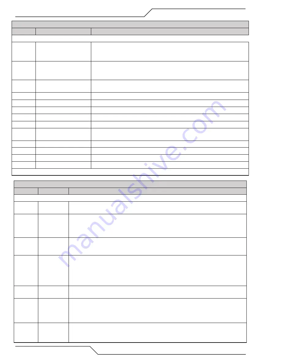
CCM Status Code
Code
Message
Remedy / Comments
Group 3 -- Gas Controller Status & Protocol
301
Gas control communication
fault
Problem with fiber optic cable to GCM 2010; Dirt on fiber ends or in connectors; blow
out with clean dry air. Fiber not locked into connector; Sharp bends in fiber cable;
Fiber defective; GCM 2010 circuit board defect;
302
Gas Control reply fault
Problem with fiber optic cable to GCM 2010; Dirt on fiber ends or in connectors; blow
out with clean dry air. Fiber not locked into connector; Sharp bends in fiber cable;
Fiber defective; GCM 2010 circuit board defect;
303
Gas Supply Pressure out of
range.
GCM 2010 inlet plasma or shield pressure low or defective pressure sensors PS3 &
PS4; Defective GCM 2010 PCB.
304
Gas Control Purging
Normal following power up or returning from Plasma Disable. Wait for purge to finish.
305
Gas Control protocol error
Verify Firmware revision for compatibility with GCM 2010
306
Not used
Reserved for other future use.
307
Gas Control sequencing error
Verify Firmware revision for compatibility with GCM 2010
308
Gas Control Type Mismatch
Wrong CCM (Auto-Cut or Pak 200 type?) for Ultra-Cut; Install correct CCM
309
Gas Control command fault
Verify Firmware revision for compatibility with GCM 2010; Electromagnetic interfer-
ence with Arc Starter; inspect grounding; bonding; and isolation
310 *
DPC fault
Check DPC status indicator for specific problem
311 *
DPC valve control fault
Check DPC status indicator for specific problem
312 *
DMC fault
Check DMC status indicator for specific problem
313 *
Gas Controller not configured. DMC or DPC not configured for a process or locked; See DMC and DPC status
* Applies to DFC 3000 (Auto Gas) only
CCM Status Code
Code
Message
Remedy / Comments
Group 4 -- Torch Coolant System
401
Coolant Level
low
Check coolant level, add as needed. Defective or disconnected level sensor.
402
Low coolant
flow
Coolant flow as measured by flow switch FS1 is less than 0.7 gpm (0.25 for Pak200i); Clogged
filter; Restriction in torch lead or head; Wrong style consumables; Bad O-ring on the torch check
valve; broken or defective torch coolant tube/check valve; Defective pump or bypass valve. 402
code along with 104 code is probably a low flow problem.
403
Coolant over-
heated
Coolant supply temperature exceeded 75 degrees Celcius (167F). Operating with side panel
loose or removed; Air flow blocked at air inlet or exit of power supply; Coolant fan failed; radiator
fins clogged with dirt.
404
Coolant System
not ready.
Proper coolant flow of 0.7 gpm as measured by flow switch FS1 was not obtained during up to
4 minutes of Priming. New installation can require additional Priming cycle(s) to fill hoses with
coolant; cylce power to restart Priming; Coolant hoses or torch hoses reversed; Clogged coolant
filter; Restriction in torch lead or head; Wrong style consumables; broken or defective torch cool-
ant tube/check valve; Defective or disconnected FS1 flow SW; Defective pump or bypass valve.
405
Low Coolant
Level Warning
Low coolant level during cut, does not stop cut.
Add coolant as required.
406
Coolant Flow
Low Warning.
This is a warning, does not stop system operation. Coolant flow rate lower than expected. Can be
caused by gas bubbles being introduced into the coolant or wrong or mismatched or worn consum-
able parts; Failed seals in torch cartridge or torch body; Clogged coolant filter; Restriction in torch
lead or head; defective or disconnected FL1 flow sensor.
407
Coolant over-
heated, high
ambient.
Coolant supply temperature exceeded 75 degrees Celsius (167 Fahrenheit) likely cause ambient
greater than 40 degrees Celsius (104 Fahrenheit); Reduce cutting duty cycle; Reduce ambient
temperature; Add separate coolant cooler.
Содержание Ultra-Cut 300 XT
Страница 6: ...This Page Intentionally Blank...
Страница 10: ...TABLE OF CONTENTS This Page Intentionally Blank...
Страница 15: ...ULTRA CUT 400 XT Manual 0 5275 SAFETY INSTRUCTIONS 1 5 This Page Intentionally Blank...
Страница 88: ...ULTRA CUT 400 XT OPERATION Manual 0 5275 This Page Intentionally Blank...
Страница 106: ...ULTRA CUT 400 XT REPLACEMENT PARTS Manual 0 5275 This Page Intentionally Blank...
Страница 114: ...ULTRA CUT 400 XT TORCH INFORMATION Manual 0 5275 This Page Intentionally Blank...
Страница 130: ...ULTRA CUT 400 XT APPENDIX Manual 0 5275 APPENDIX 8 CCM CPU PCB Layout Test Point Test Point Art A 11675_AB...
Страница 132: ...ULTRA CUT 400 XT APPENDIX Manual 0 5275 APPENDIX 9 CCM I O PCB Layout Test Point Test Point Art A 11676_AC...
Страница 134: ...ULTRA CUT 400 XT APPENDIX Manual 0 5275 APPENDIX 10 Pilot PCB Layout Art A 11677 Test Point Test Point...
Страница 136: ...ULTRA CUT 400 XT APPENDIX Manual 0 5275 APPENDIX 11 Relay and Interface PCB Layout Test Point Test Point Art A 11678_AB...
Страница 138: ...ULTRA CUT 400 XT APPENDIX Manual 0 5275 APPENDIX 12 Display PCB Layout Test Point Test Point Art A 11679...
Страница 139: ...ULTRA CUT 400 XT Manual 0 5275 APPENDIX A 25 Display PCB Test Points TP1GND TP2 5VDC TP3 24VDC...
Страница 140: ...ULTRA CUT 400 XT APPENDIX Manual 0 5275 APPENDIX 13 System Bias PCB Layout Test Point Test Point Art A 11680...
Страница 142: ...ULTRA CUT 400 XT APPENDIX Manual 0 5275 APPENDIX 14 Main Inverter Bottom PCB Layout Test Point Test Point Art A11681_AB...
Страница 144: ...ULTRA CUT 400 XT APPENDIX Manual 0 5275 APPENDIX 15 Main Inverter Top PCB Layout Test Point Test Point Art A11682_AB...
Страница 146: ...ULTRA CUT 400 XT APPENDIX Manual 0 5275 APPENDIX 16 Control and Fault PCB Layout Test Point Test Point Art A11683_AB...
Страница 148: ...ULTRA CUT 400 XT APPENDIX Manual 0 5275 APPENDIX 17 Cap Bias Bottom PCB Layout Art A 11685_AB...
Страница 149: ...ULTRA CUT 400 XT Manual 0 5275 APPENDIX A 35 APPENDIX 18 Cap Bias Top PCB Layout Art A 11686_AB...
Страница 150: ...ULTRA CUT 400 XT APPENDIX Manual 0 5275 APPENDIX 19 Suppressor PCB Layout Art A 11684_AB...
Страница 201: ...ULTRA CUT 400 XT Manual 0 5275 APPENDIX A 87 This Page Intentionally Blank...
Страница 213: ......


