


English 21
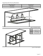
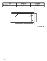
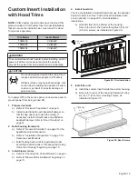
3. Build housing framework
a)
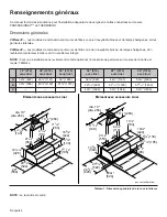
Refer to “General Information” on page 4
for the
applicable model dimensions.
b)
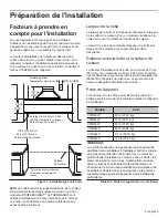
Refer to “Installation Preparation” on page 5
for
clearance specifications.
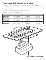
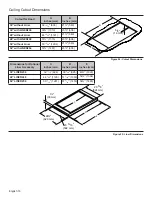
c) Build housing framework for applicable model
according to dimensions
in “Preparing the Ceiling
Cutout and Housing” beginning on page 15.
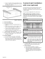
4. Install blower motor
a) Refer to
“Blower Motor Installation” beginning on
page 10
.
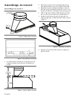
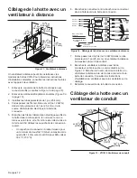
5. Hood liner installation
a) Slide the liner onto the hood (
Figure 33)
.
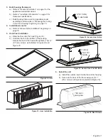
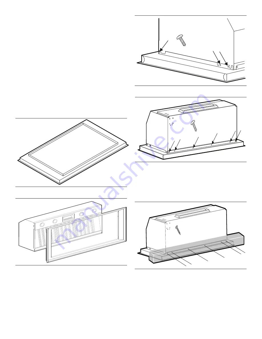
b) Hold liner flush to the bottom of the housing.
Secure the liner to the hood with eighteen (18) x
Ǫ
''
(9.5 mm) screws, as indicated in
Figure 34
and
Figure 35
.
6. Install the unit
a) Install the custom insert inside the custom housing.
b) Secure to the rear of the frame using six (6) 1''
(25.4 mm) mounting screws provided (
Figure 36
).
Figure 32: Liner
Figure 33: Liner Installation
Figure 34: Secure Liner Sides
Figure 35: Secure Liner Front & Back
Figure 36: Rear Screws
⅜" (9.5 mm)
x 3 each side
⅜" (9.5 mm)
X 6 each front
& back side
1'' (25.4 mm) X 6
mounting screws


