


English 12
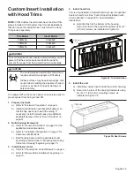
Wiring the Hood with a
Remote Blower
Custom insert models can be installed with remote blowers
(VCIN models). For complete installation instructions see
the instructions supplied with the blower unit.
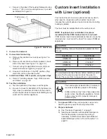
1. Remove junction box channel covering the wires (
see
Figure 7 on page 10
).
2. Remove circular knockouts (
Figure 7 on page 10
).
3. Install 1'' (25.4 mm) conduit connectors.
4. Run black, white, and green wires (#12 AWG) in 1''
(25.4 mm) conduit from the power supply to the
junction box.
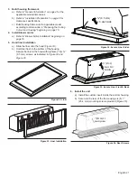
5. Connect the power supply wires to the hood wires in
the following order: black to black, white to white, and
green wire to green ground screw on chassis. Use
spring type wire nuts.
•
Spring type wire nuts, rated for a minimum of two
(2) #18 gauge wires and maximum of four (4) #14
gauge wires, UL & CSA rated to 600V and 302°F
(150°C).
6. Connect the “pigtail” to the connector inside the
junction box.
7. Close the junction box cover.
8. Run five (5) #14 AWG wires in 1'' (25.4 mm) conduit
from the remote blower to the second conduit
connector.
9. Connect the remote blower to the pigtail wires as
shown in
Figure 12
. Connect the remote blower green
(ground) wire to the ground screw in the junction box.
Refer to the blower installation instructions for further
wiring details.
Wiring the Hood with an
Inline Blower
Both VCIN and VCIB custom insert models can be installed
with inline blowers. For complete installation instructions
see the instructions supplied with the blower unit.
1. Remove junction box channel covering the wires (
see
Figure 7 on page 10
).
2. Remove circular knockouts (
Figure 7 on page 10
).
3. Install 1'' (25.4 mm) conduit connectors.
4. Run black, white, and green wires (#12 AWG) in 1''
(25.4 mm) conduit from power supply to junction box.
5. Connect the power supply wires to the hood wires in
the following order: black to black, white to white, and
green wire to green ground screw on chassis. Use
spring type wire nuts.
•
Spring type wire nuts, rated for a minimum of two
(2) #18 gauge wires and maximum of four (4) #14
gauge wires, UL & CSA rated to 600V and 302°F
(150°C).
Figure 11: VTR1330 Remote Blower
Figure 12: Wiring the Hood with a Remote Blower
19
7/8
"
(505)
2
1/8
"
(54)
10"
(254)
2
1/8
"
(54)
20
3/4
"
(527)
12
7/8
"
(327)
12
1/8
"
(308)
6
1/2
"
(165)
1
7/8
"
(48)
13
5/8
"
(346)
dia. 9
7/8
"
(251)
SPEED 1
SPEED 2
SPEED 3
NEUTRAL
RD
BU
BN
WH
SP4
GROUND
N
SP1
SP2
SP3
Brown
Brown
Brown
Green/Yellow
Green/Yellow
Green/Yellow
White
White
White
Red
Red
Red
Blue
Blue
Blue
Orange
Orange
Orange
WH / BC / BL (16 AWG)
BK / N / NE (16 AWG)
120V, 60HZ, 20A
POWER SUPPLY
L1
N
T1
T2
S3
Figure 13: VTI1010 Inline Blower
12
1/8
"
(308)
14
3/8
"
(365)
7/8
" (22)
1
3/4
"
(44)
19
1/8
"
(486)
ø 9
7/8
"
(251)
12
"
(305)
12
7/8
"
(327)


