


Texmate, Inc. Tel. (760) 598-9899 • www.texmate.com
Page 26
Apr-18-2016 DI-60A 320 DS (NZ302)_UL April 2016
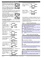
Code 5 is a single code that
combines all the configuration
and post processing functions
available for Channel 3.
When a
triple input
signal
conditioner is installed, the 3rd
input signal is processed and
displayed on CH3.
Post processing and measure-
ment task functions for CH3
are configured in the 1st, 2nd,
and 3rd digits of Code 5. The
diagram opposite lists the
available configuration selec-
tions in Code 5.
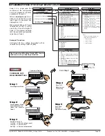
Example Procedure:
Configure CH3 to display the square root of a
voltage input by setting Code 5 to [
11X
].
Prog.
SP1
SP2
SP4
SP3
SP5
SP6
Prog.
SP1
SP2
SP4
SP3
SP5
SP6
Press
1
Prog.
SP1
SP2
SP4
SP3
SP5
SP6
Prog.
SP1
SP2
SP4
SP3
SP5
SP6
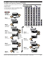
CONFIGURE
CH3 FUNCTIONS
Prog.
SP1
SP2
SP4
SP3
SP5
SP6
Prog.
SP1
SP2
SP4
SP3
SP5
SP6
Prog.
SP1
SP2
SP4
SP3
SP5
SP6
Prog.
SP1
SP2
SP4
SP3
SP5
SP6
Prog.
SP1
SP2
SP4
SP3
SP5
SP6
Step 1
Step 2
Step 3
Operational Display
Operational Display
Press
6
Press
at same
time
Press
at same
time
OR
Step 4
Press
at same
time
Press
at same
time
Step 5
CONFIGURING CH3 FUNCTIONS PROCEDURE
Pass Brightness Mode,
Calibration Mode, and
Codes 1 to 4 and enter
Code 5
From Step 4
Set Code 5 to [11X]:
1st Digit = 1 Selects square root of CH3
2nd Digit = 1 Selects voltage, current
3rd Digit = X Not relevant
Save CH3 setting
Exit Code 6.
Return to
Operational Display
Enter Brightness Mode
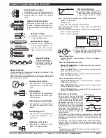
FOR THERMOCOUPLE
0 Type J
1 Type K
2 Type R
3 Type S
4 Type T
5 Type B
6 Type N
7 Select user defined lineariza-
tion table (Table 1) set up in CAL
[24X]
FOR RTD TYPE (2-, 3-, 4- WIRE)
0 Resistance
1 RTD 385
2 RTD 392
3 RTD 120
4 Cn 10
MEASUREMENT TASK
0 No Function
1 Voltage / current
2 TC (3rd digit selects type of TC)
3 RTD (3rd digit selects type of RTD)
4 Real Time Clock & Timer (3rd digit selects type)
5 -
6 -
7 Smart Input Module (3rd digit selects register)
CODE 5 – CHANNEL 3 FUNCTIONS
FIRST DIGIT
SECOND DIGIT
THIRD DIGIT
FOR REAL-TIME CLOCK & TIMER
0 HRS:MIN:SEC
1 HRS:MIN
2 -
3 -
4 1 2nd Count UP Timer
5 1 2nd Count DOWN Timer
6 -
7 -
FOR SMART INPUT MODULE
0 Output Register 1
1 Output Register 2
2 Output Register 3
3 Output Register 4
4 Output Register 5
5 Output Register 6
6 Output Register 7
7 Smart Input Module Register 2
Code Setup
Press
Use the
buttons to set the
required smart input module code
(0 to 377). See
I-Series Input
Modules Guide (Z87)
for code
details.
0 Direct Display of
Input (no processing)
1
Square Root of
Channel 3
2 Inverse of Channel 3
3
4 kB Meters
32-point Linearization
of CH3 using Table 1
32 kB Meters
32-point Linearization
of CH3 using Table 3
Note:
All linearization
tables are set up in
the Calibration Mode
[24X].
CH3 POST PROCESSING
START HERE
Initial Setup Procedures
[CodE_5] - Channel 3 Functions
See
I-Series Input Modules Guide (Z87)
for pro-
cedures to set up a triple input module.
P


