background image

Texmate, Inc. Tel. (760) 598-9899  •  www.texmate.com

Page 36

Apr-18-2016  DI-60A 320 DS (NZ302)_UL April 2016

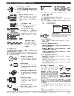
Registers That Can Be Selected By Front Panel Push Button Programming

A Tiger 320 Series meter has 6,144 registers which are 
provided for use by the operating system and the powerful 
Custom Macro Programming system.

40 Manually Selectable Registers

Using the front panel buttons, there are 40 registers that 

may be selected for use within the following functions:

• [

CodE_1] - Display Configuration [X50]

. Selection of a 

register as the data source for displays, peak and valley, 
totalizers and analog outputs. (See pages 18 & 19)

• 

Setpoint Control Settings [X1X]

. Selection of a register 

as the data source for a setpoint. (See Page 34 )

• 

Setpoint Control Settings [XX7]

. Selection of a desti-

nation register that is to be reset by a setpoint with the 
contents of a selected source register. (See Page 35)

• 

Setpoint Control Settings [XX7]

. Select which register’s 

contents are to be copied into the destination register by 
a setpoint. (See Page 35)

The 40 registers that can be selected as a data source, a 
reset source or a reset destination for the functions above 
are shown in the table on the right. 

The table shows, in seven columns, the functions where 
these registers can be used.  
Where a register is more likely to be used in a particular 
function, a closed circle 

●  

is shown in the column. For those 

functions where a register is less likely to be used, an open 
circle 

°

 is s hown.

No register number is shown for the first 11 functions, 
because these 11 functions are identified in the display 
menu for direct selection by their code names. 
When cycling through the Registers Menu and then 
Registers 1 to 244, the numerical Register Set will incre-
ment through each decade in turn, from 1 to 0, while the 
button is held down. When [200] is reached, [oFF] or [tArE] 
will be displayed. To select a specific number set, the button 
should be released and pressed again each time the left 
most decade displays the desired number for that decade.
To quickly exit the numerical 1 to 244 Register Set, hold the   

 button down while cycling through the decades, and 
release it when [oFF] or [tArE] appears.

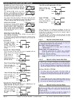
Registers that Should Not be Used

The following registers are contained within the selectable 

1 to 244 Register Set, but they should not be selected 

because they are either reserved for future use, or for use 

by the operating system only:

15, 38, 47-48, 52-53, 61-64, 123-128, 140-141, 234-244

Any selection of these Registers may cause a malfunction.

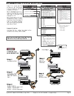
Resetting and Incrementing Using Setpoints

Setpoints may be used to reset and/or increment registers. In 
the example shown below, 2 liter soft drink bottles are being 
filled and packed 12 to a case. Using the setpoint reset and 
increment feature, the number of bottles and the total number 
of filled cases is easily calculated and displayed.  Totalizer 1 
counts from 0 to 2, resets, and repeats. CH 2 counts from 0 to 
12, resets, and repeats.

Flow

Sensor

Channel 1

Flow Rate

Channel 3

Filled Cases

Totalizer 1

Flow

Channel 2

Bottles

SP5 = 2.00
Hi Setpoint  

SP6 = 2.00
Hi Setpoint  

SP4 = 12
Hi Setpoint  

SP3 = 12
Hi Setpoint  

S

O

U

R

C

E

R

E

S

E

T

R

E

S

E

T

I

N

C

R

E

M

E

N

T

I

N

C

R

E

M

E

N

T

S

O

U

R

C

E

S

O

U

R

C

E

S

O

U

R

C

E

USING SETPOINTS TO INCREMENT AND RESET REGISTERS

P

Use the   and   buttons to 
cycle through the Registers Menu 
and Registers (1 to 244). Press 
the 

P

 button to make a selection.

[rESLt]

[Ch1]

[Ch2]

[Ch3]

[Ch4]

[tot_1]

[tot_2]

[PEAK]

[tArE]

[VALEY]

[diSP]

[  1]

[ 10]

[100]

[200]

[244]

Data

Source

for

Analog

Outputs

1 & 2

Data

Source

for

Setpoints

Reset

Dest.

Reset

Source

Data

Source

for

Totalizers

1 & 2

Register Functions Register

Numbers

Data

Source

for

Displays

Data

Source

for

Peak &

Valley

Display [diSP] 


Result [rESLt] 


CH1 [Ch1] 


CH2 [Ch2] 


CH3 [Ch3] 


CH4 [Ch4] 


Total 1 [tot_1] 


Total 2 [tot_2] 


Peak [PEAK] 

° 


 ° 

Valley [VALEY] 

° 


 ° 

Tare [tArE] 

° 

° 

° 


° 

° 

PID Output 1 

50 

° 

° 

° 


° 


PID Output 2 

51 

° 

° 

° 


° 


Smart Result 1 

54 

° 

° 

° 


°

Smart Result 2 

55 

° 

° 

° 


°

Smart Result 3 

56 

° 

° 

° 


°

Smart Result 4 

57 

° 

° 

° 


°

Smart Result 5 

58 


°

Smart Result 6 

59 


°

Smart Result 7 

60 


°

Analog Output 1 

83 

° 


° 

° 

°

Analog Output 2 

84 

° 


° 

° 

°

Timer 1 

95 

° 


° 

° 

°

Timer 2 

96 

° 


° 

° 

°

Smart Reset Offset 1  121 


Smart Reset Offset 2  122 


Clock - Seconds 

213 


°

Clock - Minutes 

214 


°

Clock - Hours 

215 


°

Clock - Days 

216 


°

Clock - Date 

217 


°

Clock - Month 

218 


°

Clock - Year 

219 


°

Setpoint 

Latch 

221 


Relay 

De-energize 

222 


Zero Offset - Result 

227 


°

Zero Offset - CH1 

228 


°

Zero Offset - CH2 

229 


°

Zero Offset - CH3 

230 


°

Zero Offset - CH4 

231 


°

Содержание DI-60AE

Страница 1: ...dback and PID output Scalable from 1 count to full scale Dual independent totalizers to integrate input signals 6 super smart independently programmable setpoints with 8 selectable functions including...

Страница 2: ...smart setpoints with fully configurable hysteresis on and off delays one shot pulse and repeat timers latching dual PID setpoint tracking resetting of registers initiat ing of logging and printing Sig...

Страница 3: ...ngle Analog Output Fully scalable from 4 to 20mA or 0 to 20mA or reverse and selectable for 0 to 10VDC or reverse 2 Dual Analog Output Fully scalable from 0 to 10VDC or reverse Outputs continued Analo...

Страница 4: ...ta source for OUTPUT PROCESSING Select data source for Setpoint 1 2 3 4 5 6 Analog output 1 2 Data logging Select data source for DISPLAY PROCESSING Select data source for Display 1 Default Display Ch...

Страница 5: ...Page 5 Apr 18 2016 DI 60A 320 DS NZ302 _UL April 2016 Texmate Inc Tel 760 598 9899 www texmate com THIS PAGE INTENTIONALLY LEFT BLANK...

Страница 6: ...total 2 Once into the viewing routine pressing the button moves through each displayed parameter See Display with Faceplate and Bezel diagram Annunciator LEDs The annunciator LEDs can be programmed to...

Страница 7: ...have to be connected to the COMMON pin pin 11 The LOCK pin can also be configured in Code 9 to carry out the following functions see Meter Programming Codes on Page 9 Reset channel 1 XX1 Reset channel...

Страница 8: ...indicates that the buttons must be pressed at the same time The only exception to this rule is when carrying out the Model and Software Code Version Check Programming procedures are graphic based with...

Страница 9: ...P The Setpoint and Relay Control Settings diagram on Pages 34 and 35 shows the three digit config uration settings that are applied individually to each setpoint See Page 33 for an example proce dure...

Страница 10: ...lowing selected on demand modes On Demand Modes Tare Single point calibration Two point calibration Primary input compensation Manual loader manual offset Print View Mode SP_1 SP_3 SP_5 PEAK TOT_1 CH3...

Страница 11: ...eventing them from being reprogrammed Any codes that have not been blanked out are still visible and can be reprogrammed Turning code blanking OFF means all meter programming codes are visible when yo...

Страница 12: ...Display Operational Display Example OR Press at same time Press at same time Press at same time Press at same time Enter Brightness Mode Adjust brightness to 7 Save brightness setting Exit Brightness...

Страница 13: ...odule Note This function is not available on all input modules 5 Calibrate Analog Output requires multimeter con nected to pins 16 and 17 6 7 0 Serial Communications Properties 1 Set Auto Zero Mainten...

Страница 14: ...m 1 to 255 samples The averaging window can be set to between 1 and 65535 counts See the calibration modes diagram on Page 13 showing a breakdown of 1st 2nd and 3rd digits See Input Signal Sampling Sh...

Страница 15: ...the HIGH input signal Select the No Function Calibration Mode 000 Save Calibration Mode 000 setting and enter Code 1 Exit code 1 and return to operational display 5 1 Adjust display to desired readin...

Страница 16: ...6 To Step 7 OR From Step 6 OR OR Press 1 Press 1 Press 1 Press 1 Press 1 Press at same time Press at same time Press at same time Press at same time Step 1 Step 2 Step 3 Step 4 Step 5 Step 6 Step 7 St...

Страница 17: ...Functions Mode The display functions mode is configured by changing the 2nd and 3rd digits in Code 1 Selecting X5X enters the Data Source sub menu Selecting X6X enters the Display Format sub menu Sele...

Страница 18: ...eter the values for setpoint 5 and setpoint 6 are activated as upper and lower limits See Analog Output Supplement for further details Note 1 LED annunciators are always off except when the meter is i...

Страница 19: ...CONFIGURE DATA SOURCE Go to Source selection Go to the next selection Example Procedure Configure the Primary Display with the display diSP as the data source by setting Code 1 to X50 See diagram at t...

Страница 20: ...ons setting Enter Brightness Mode Pass Brightness and Calibration Modes and enter Code 1 Save entered value Save Code setting 0 No rounding 1 Rounding by 2 s 2 Rounding by 5 s 3 Rounding by 10 s Confi...

Страница 21: ...Operational Display Operational Display Example Press 2 Press at same time Press at same time Press 1 OR Step 4 Press at same time Press at same time Step 6 Prog SP1 SP2 SP4 SP3 SP5 SP6 Prog SP1 SP2...

Страница 22: ...nciators Procedure Prog SP1 SP2 SP4 SP3 SP5 SP6 Prog SP1 SP2 SP4 SP3 SP5 SP6 Prog SP1 SP2 SP4 SP3 SP5 SP6 Prog SP1 SP2 SP4 SP3 SP5 SP6 X X Prog SP1 SP2 SP4 SP3 SP5 SP6 CONFIGURE UPDATE AT SAMPLE RATE...

Страница 23: ...pe of TC 2 RTD 3 wire 3rd digit selects type of RTD 3 RTD 2 or 4 wire 3rd digit selects type of RTD 4 Frequency 5 Period 6 Counter 7 Smart Input Module CODE 2 CHANNEL 1 MEASUREMENT TASK AND SAMPLING R...

Страница 24: ...ith or without a Day Month Year or Hours Minutes Seconds time stamp Time stamp settings are configured in Code 8 Post processing functions refer to functions that occur to the input after it has been...

Страница 25: ...surement task and 32 point linearization for CH2 is config ured in the 1st and 2nd digits of Code 4 The diagram opposite lists the available configuration selections in Code 4 Example Procedure Config...

Страница 26: ...t X Not relevant Save CH3 setting Exit Code 6 Return to Operational Display Enter Brightness Mode FOR THERMOCOUPLE 0 Type J 1 Type K 2 Type R 3 Type S 4 Type T 5 Type B 6 Type N 7 Select user defined...

Страница 27: ...Time Clock and Timer 3rd digit selects type 5 6 7 Smart Input Module 3rd digit selects register FOR SMART INPUT MODULE 0 Output Register 1 1 Output Register 2 2 Output Register 3 3 Output Register 4...

Страница 28: ...sult using Table 2 See Note 5 3 32 point Linearization on Result using Table 3 See Note 5 4 32 point Linearization on Result using Table 4 See Note 5 5 125 point Linearization on Result Tables 1 to 4...

Страница 29: ...S LOG OR PRINT TRIGGER 0 No trigger 1 Trigger on Demand from PROGRAM Button 2 Trigger on Demand from F1 Button 3 Trigger on Demand from F2 Button 4 Trigger on Demand from HOLD Pin 5 Trigger on Demand...

Страница 30: ...y output modules support a combination of 4 5 A Form A and 9 10 A Form C relays providing 12 configuration options A solid state relay SSR output module supports 300 V 210 mA DC SSRs A 22 opto isolate...

Страница 31: ...can be programmed in relay latching modes Setpoint Reset Trigger Setpoints can be programmed to reset selected registers or be manually reset They can also trigger a data print or a data log DUAL PID...

Страница 32: ...N Pulsed OFF Modes These are delay modes were the relay is normally on and pulses off when the setpoint activates 1 Shot OFF mode Programmable Minimum OFF time SP ON SP OFF 1 Shot OFF Mode Prog Min OF...

Страница 33: ...ly cycle thru SPC_1 Save SP1 control settings Operational Display Operational Display Exit SPC_2 and return to operational display Save SP1 activation value setting Select CH1 as the SP1 activation so...

Страница 34: ...setpoint value with RISING INPUT SIGNAL INITIAL START UP INHIBIT SP Activation Source 0 Activate Setpoint Source from Selected Register 1 Select Source for Setpoint Note X1X is a register selection pr...

Страница 35: ...o XX0 DOM 0 0 to 6553 5 secs Minimum on time M_on 0 0 to 6553 5 secs On time on _t 0 0 0 001 to 6553 5 65 535 secs DOB 0 0 to 6553 5 secs Off time oFF_t 0 0 0 001 to 6553 5 65 535 secs DOB 0 0 0 001 t...

Страница 36: ...t hold the button down while cycling through the decades and release it when oFF or tArE appears Registers that Should Not be Used The following registers are contained within the selectable 1 to 244...

Страница 37: ...r HI Voltage Fuse for LO Voltage Isolated Feed Back Isolated Switching Power Supply Controller 5 VDC 18 VDC ISO 5 VDC 5 VDC 5 VDC GND 24 VDC GND LC Filter 1 2 3 4 5 6 7 8 9 10 RELAY MODULES NO3 COM 1...

Страница 38: ...29 27 26 25 Options 4A 4A Order Code OR11 OR12 OR23 OR14 4A 4A 4A 4A 10A OR15 OR16 SP2 SP4 SP1 SP3 9A 9A 9A 9A 9A 9A 9A 9A SP3 SP1 SP4 SP2 Relay Modules with up to two 4 5A Form A Relays and up to tw...

Страница 39: ...and process control applications Modular construction ensures you don t have to pay for unnecessary hardware Simply order the input and output options to suit your application Input Signal Conditioni...

Страница 40: ...20V 2V SPAN Increase Decrease ON OFF 24V Exc Input Signal Conditioner Main PCB Shown with optional Input Signal Conditioning Module Ordered Separately Hi Volt Order Code PS1 Lo Volt Order Code PS2 ID0...

Страница 41: ...oisy components Shielding cables for input output leads is recommended with shield connection to earth ground near the meter preferred 4 A circuit breaker or disconnect switch is required to disconnec...

Страница 42: ...3 Code 3 Channel 1 Post Processing and Serial Mode Functions 24 Code 4 Channel 2 Measurement Task and Sampling Rate 25 Code 5 Channel 3 Functions 26 Code 6 Channel 4 Functions 27 Code 7 Result Process...

Страница 43: ...d Not Be Selected 36 Resetting and Incrementing Using Setpoints 36 Relay Logic Output Modules 38 Serial Communication Configuration 24 Pinouts 38 Setpoint Programming Mode 30 35 Data Logging 31 Data P...

Страница 44: ...xmate com Texmate has facilities in Japan Taiwan and Thailand Case Dimensions Clear Lockable NEMA 4X Splash Proof Cover P N OP N4 96x48 The 96x48mm case is particularly suitable for mounting in mosaic...

Отзывы: