background image

Premier Elite Series


Quick Start Guide


INS222-10 

10: Confirm Devices 

The  "Confirm  Devices"  menu  will  appear  check  and  make  sure  all 
installed  Keypads  and  Expanders  are  showing,  press 

/


and 

/

 again to confirm. 

11: Learn & Place Ricochet Devices 

Once  the  panel  is  powered  up  you  will  be  prompted  to  learn  any 

Ricochet  devices  to  the  system.  Devices  should  be  learnt  local  to 

the receiver, and placed in their selected locations starting with the 

one closest to the receiver. 

12: Programming the Control Panel 

Please refer to section 5 for instruction on programming the control 

panel. 

13: Testing the System 

Test the system thoroughly to ensure that all features and functions 

operate as required (see page 19 for details). 

Wiring & Addressing Network Devices

Connecting Devices to the Network 

Before  connecting  keypads,  zone  expanders  and  output  modules, 

isolate ALL power from the control panel (AC Mains & Battery). Do 

not continue if there is still power present on the control panel. 


Connecting  devices  with  power  still  present  on  the  control  panel  may 
damage the device or control panel and invalidate any warranty. 

Keypads,  expanders  and  output  modules  are  all  connected  to  the 

network terminals located at the bottom left hand corner of the control 

panel  PCB,  and  may  be  connected  serially  (daisy  chain),  in  parallel 

(star) or any combination of the two  


No  more  than 8  zone  expanders, 8  keypads and 4 output  modules  can be 
connected  to  each  network.  The  maximum  number  of  devices  that  can  be 

connected in total will depend on the control panel fitted.  

Wiring the Network 

The  networks  are  made  up  of  four  terminals  incorporating  power 

and  data.  To  ensure  correct  operation,  all  four  terminals  on  the 

device  must  be  connected  to  the  corresponding  terminals  on  the 

control panel, or previous device  

Terminal 

Description 

+12V Supply 

0V Supply 

Transmit Data 

Receive Data 

Devices can be connected using 4-core cable. However, it is recommended 

that 6 or 8-

core cable is used as the spare cores can be used to ‘Double Up’ 

on the power connections if needed. 

Stranded tinned annealed copper BS4737 7/0.2 alarm cable can 

be used for most installations. However, under certain 

conditions it may be necessary to use screened cable of the 

same specification. 

PLEASE NOTE. The conductor resistance should be no greater 

than 8

 per 100metres. 

The usage of Low grade TCCA (tinned copper clad cable) can 

have a detrimental effect on the operation of the system and the 

cable distances specified in this manual. 

Cable Distances 

The  maximum  recommended  distance  for  devices  when  using 

standard 7/0.2 alarm cable is: 


250m  for  each  branch  when  using  the  star  (parallel) 

configuration 


When using a daisy chain (series) configuration the maximum 

distance will depend  on  the  number  of  devices  connected  on 

the  chain.  Whichever  method  of  wiring  configuration  is  used, 

ensure  that  the  voltage  between  the  ‘+’  and  ‘–’  term

inals  at 

each device is no lower than 10.0V when the system is running 

on the standby battery. 


Wireless  expanders/panels  should  be  mounted  at  least  50cm 

away from metallic surfaces. 


Configuration 

Max. Cable Run 

1. 

Keypad  + 2 PIR’s @15mA


250m 

2. 

Ex 2 PIR’s @15mA


250m 

3.


Ex 8 PIR’s @15mA


100m 

4.

 As No. 3 + 16

 Speaker  

30m 

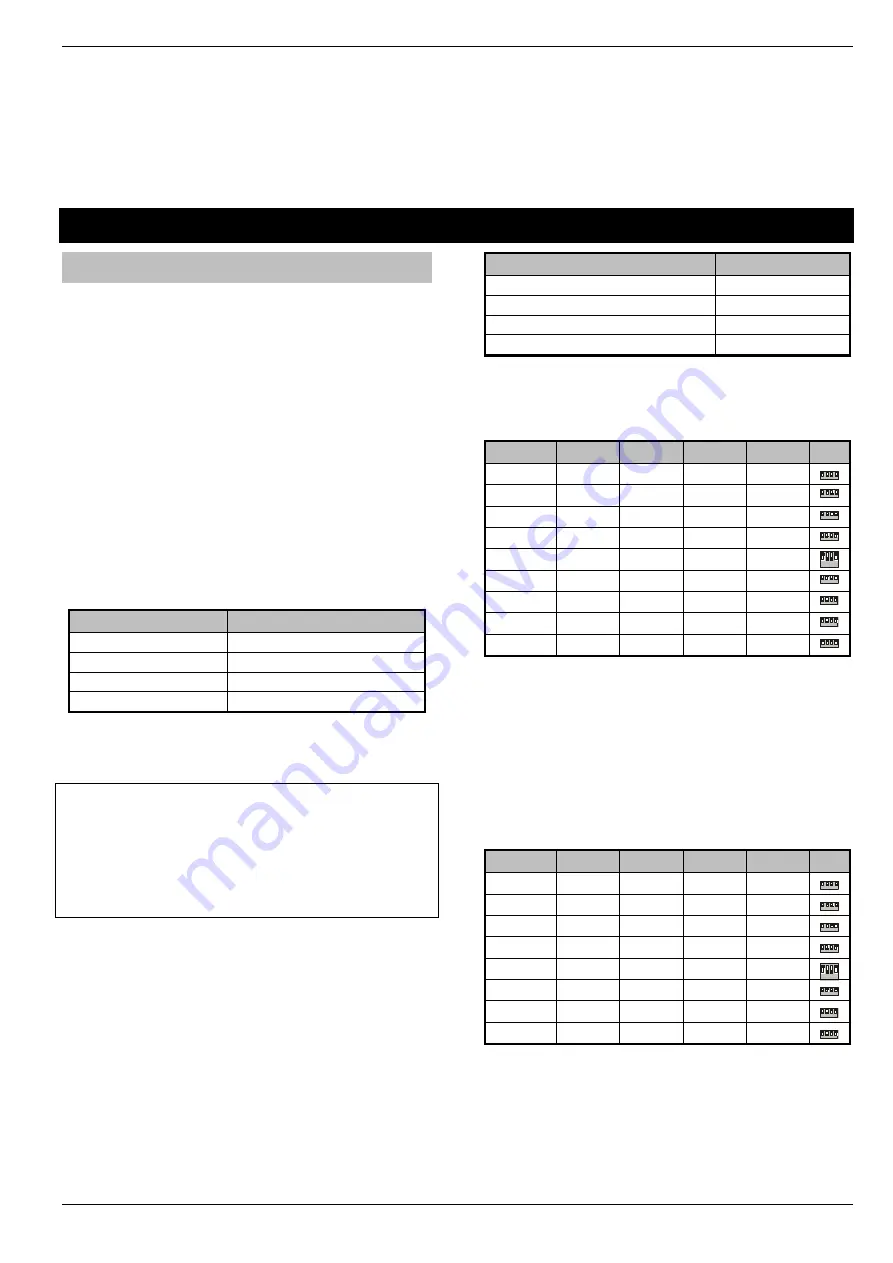
Keypad Addressing 

Each  keypad  must  be  assigned  a  different  address  using  the  DIL 

switches located on the left hand side of the PCB.  

Address 

DIL 1 

DIL 2 

DIL 3 

DIL 4 


On 

or off 

Off 

Off 

Off 


2


4


3


1


Off 

On 

Off 

Off 


2


4


3


1


Off 

Off 

On 

Off 


2


4


3


1


Off 

Off 

Off 

On 


2


4


3


1


 5 * 

On 

Off 

Off 

On 


2


4


3


1


 6 * 

Off 

On 

Off 

On 


2


4


3


1


 7 * 

Off 

Off 

On 

On 


2


4


3


1


 8 * 

On 

Off 

On 

On 


2


4


3


1


Engineers 

On 

On


On 

On 


2


4


3


1


Never  set  two  keypads  on  the  same  network  to  the  same 
address. 

When 

using  a  keypad  as  an  Engineer’s  keypad,  the  DIL 

switches must all be ‘On’.


* 88 168 & 640 only 

Expander Addressing 

Each Expander must be assigned a different address using the DIL 

switches  located  in the  centre  of  the  PCB.  The  table below  shows 

the expander addressing: 

Address 

DIL 1 

DIL 2 

DIL 3 

DIL 4 


1* 

On 

or off 

Off 

Off 

Off 


2


4


3


1


2* 

Off 

On 

Off 

Off 


2


4


3


1


3** 

Off 

Off 

On 

Off 


2


4


3


1


4** 

Off 

Off 

Off 

On 


2


4


3


1


5*** 

On 

Off 

Off 

On 


2


4


3


1


6*** 

Off 

On 

Off 

On 


2


4


3


1


7*** 

Off 

Off 

On 

On 


2


4


3


1


8*** 

On 

Off 

On 

On 


2


4


3


1


Never  set  two  expanders  on  the  same  network  to  the  same 
address. 
* 24/48/64/88/168/640 

** 48/64/88/168/640 only 

*** 88 168 & 640 only 

Содержание Premier Elite Series

Страница 1: ...INS222 10 Premier Elite Series Quick Reference Guide ...

Страница 2: ... each step 1 Design the Layout Make a rough sketch of the premises to get an idea of where the alarm detection devices keypads zone expanders etc are to be located 2 Mounting the Panel The control panel should be mounted in a dry area close to an unswitched AC power source and the incoming telephone line if using a communicator Mount the control panel on a flat plumb wall using at least three scre...

Страница 3: ...randed tinned annealed copper BS4737 7 0 2 alarm cable can be used for most installations However under certain conditions it may be necessary to use screened cable of the same specification PLEASE NOTE The conductor resistance should be no greater than 8Ω per 100metres The usage of Low grade TCCA tinned copper clad cable can have a detrimental effect on the operation of the system and the cable d...

Страница 4: ...ould be programmed as Double Pole EOL see page 6 When using this configuration no more than 10 detectors can be connected to each zone Triple End Of Line TEOL Use this wiring configuration when connecting PIR devices with that require Anti Mask and Fault detection Several zone wiring programming options are available for this Triple EOL is illustrated below see page 6 When using this configuration...

Страница 5: ...rams and full descriptions of all available options and functions are detailed in INS176 Premier Elite Installation Manual available on the enclosed CD or from our website Default Codes Log Off Engineer Press to log out of the Engineer Programming menu Main Menu Top Line Menu Structure Premier Elite 12 13 16 Tue 26 YES to Select Zone Setup 1 YES to Select Area Programming 2 YES to Select Global Op...

Страница 6: ...uard Access U Exit Terminator 5 24Hr Audible U Moment Key 6 24Hr Silent U Latching Key 7 PA Audible U Security 8 PA Silent U Omit Key 9 Fire U Custom Zone Attributes 1 Press to edit to select an attribute to accept O Omittable 3 Part 3 Omit F Force Omit A Access 1 Part 1 Omit E Entry Exit 2 2 Part 2 Omit G Guard Zone Attributes 2 Press to edit to select an attribute to accept D Double Knock R Rese...

Страница 7: ...Zone Chime Press to alter chime tone to go to the next option Silent Chime 1 Chime 2 Chime 3 Zone Test Press to alter Test option to go to the next option Zone Wiring Press to alter wiring type to accept Normally Open Triple EOL 2K2 4K7 6K8 Normally Closed 1K 1K 3K 4K7 4K7 Double Pole EOL 4K7 6K8 12K WD Monitor Zone Group Press to alter Zone Group to select a group to accept Elite12 24 2 Groups El...

Страница 8: ...ng an mode to accept Entry Exit Instant Exit Term Deferred Timed Exit Area Arm Suites 12 24 48 64 88 168 Use to select a suite no to edit to select an area all areas A A areas A H and I P to accept Area Arm Suites 640 Use to select a suite no to edit s P to select an area group 1 4 use A A to select areas A H and I P to accept Area Suite Text Use to select a suite to edit to select characters pred...

Страница 9: ...Fob After Entry 13 Anti code Reset 33 Armed Coms 14 Phone Line Fault 34 2 Wire Smoke 15 Arm With L Fault 35 Fault Eng Reset 16 AC Mains Fail 36 L Fault Eng Rst 17 Arm With AC Fail 37 AC Fail Eng Rst 18 Full Arm Coms 38 Anti Masking When Armed 19 Part Arm Coms 39 No Arming Before Time Arm Areas Use to select an area to toggle between the arm and disarm timer to select timers to accept Area Text Use...

Страница 10: ...r Reset 50 Confirmed Hold Up 2 Active PA Zones 09 NVM is Unlocked 30 Auto AV Outputs 51 Max Log Messages 3 10 User Engineer 31 System Clock 50Hz 52 Code Entry Timed 11 Chime Audible 32 80 Column Printer 53 PD6662 2010 12 Allow Omitting of Tampers 33 Disable Text 54 Auxiliary Input Tamper 13 Enable Online Printing 34 Enable EN50131 1 Requirements 55 Part Arm Squawk 14 Hide Activity Faults 35 First ...

Страница 11: ... Use the key to select the same option for different zones Use the key to edit the selected option use the to change the option and to confirm selection U Keypad Setup Areas 12 24 48 64 88 168 Use to select keypad to select network to edit to select an area all areas A A areas A H and I P to accept Areas 640 Use to select keypad to select network to edit s P to select an area group 1 4 use A A to ...

Страница 12: ...network to edit s P to select an area group 1 4 use A A to select areas A H and I P to accept Text Press to edit text to select characters predictive text is on by default but may be altered as described below to accept 1 M N O 6 Move Cursor A B C 2 P Q R S 7 Copy Text to Memory D E F 3 T U V 8 s P Paste Text from Memory G H I 4 W X Y Z 9 Upper Lower Case Predictive Text Numerical J K L 5 0 _ Auxi...

Страница 13: ...t group to enter output type to enter House device Number to accept Key Output Group Outputs Types Not Used Press to accept System Use to enter an output type or use to search to accept 00 ATS Path Fault 23 Custom 1 Stage B 44 Com Port Fault 01 Mains Power Off 24 Custom 1 Stage A or B 45 Radio Jamming 02 Power Output Fault 25 Custom 2 Stage A 46 Radio RX Tamper 03 Bell Tamper 26 Custom 2 Stage B 4...

Страница 14: ...ss 35 24Hr Omit 60 Armed Alarm 11 Fire Alarm 36 Reset Required 61 Intruder Alarm 12 Medical 37 Door Strike 62 Speaker Mimic 13 Auxiliary Alarm 38 Chime Mimic 63 Full Arm Exit 14 Tamper Alarm 39 Chime Enabled 64 Detector Fault 15 Alarm Abort 40 Double Knock Active 65 Detector Masked 16 Ready 41 Beam Pair 66 Fault Present 17 Entry Mode 42 Zone on Test 67 LED Control 18 2nd Entry Mode 43 Test Failed ...

Страница 15: ...otocol to accept Disabled SIA Level II Speech Module Fast Format EasyCom Pager Texecom Connect Contact ID SMS Primary Number Press to edit to enter telephone number to accept Secondary Number Press to edit to enter number to accept Account Number Press to edit to enter number to accept Dialling Attempts Press to edit to enter number to accept Reporting Channels Press to edit to select channels to ...

Страница 16: ...option to accept A Attended Download L Restrict Download when Armed M Manual Call back A Download when Part Armed D 2 Call Answer Phone Defeat K Online RKP Off Rings Required Press to edit to enter number of rings to accept UDL Dial Attempt Press to edit to enter number of dialling attempts to accept Area Accounts Use to select an area to edit to enter account number to accept Setup Modules Press ...

Страница 17: ...erse Signal View only Bit Error Rate View only Cyclic Redundancy View only GSM Signal BER View only Com1 2 3 Press R R to reset com port Com Port Setup Onboard Digi Port Com Ports 1 2 3 Use to select a com port to edit to select an option to accept Nothing Fitted Radio pad WebWayOne Emizon Module Com300 GSM Module X 10 Control Com2400 Crestron System IRIS IP Module ComISDN SIP SmartCom ComIP Radio...

Страница 18: ... to edit to select an option to change option to accept U User Menu V Vacation C Duress Code E Eng Program S Door strike O Open Close D Dual Code R Call Rem PC User Config only available to Custom users with User Menu Press to edit to select an option to change option to accept C Change Code S System tests A Add Eng Code Z Chime Zones U Setup Users N NVM Locking T Change Timer E Eng Access User Ti...

Страница 19: ...3 View Zone Status 4 System Tests 5 Confirm Devices 6 View RKP Status 7 View Exp Status Use the Numerical keys or to select the option 9 YES to Select Engineer Utils 8 Set System Time 9 Set System Date U Location Text U Print Log Data U Soak Test Areas U Change Eng Code U Adjust Volumes U Default NVM Data U View iD Data U Configure Radio U Ricochet Diag U Signalling Test U View Unique ID ...

Страница 20: ...uts errors to test zones B O to test sounder to test outputs Set System Time Use to enter time 24 hour format to accept Set System Date Use to enter date to accept Location Text Press to view Location Text Print Log Use to enter number of events to be printed to print log Start Soak Test Use to select an area all areas A A areas A H and I P to accept to start test Change Eng Code Use to enter a co...

Страница 21: ...cases when entering the Learn menu the next available free Zone will be chosen to learn a device too It will not be possible to learn a device to a Zone that already has a device learned too it The number of expander s on the system will dictate which next free zone is chosen to learn too When all device slots have been used the following screen will be shown All Devices Learnt Pressing the N Nkey...

Страница 22: ...ed in their final location Whilst it is possible to learn at any point during the programming of the system learning and testing the functionality of the Premier Elite SmartKey after all devices have been placed will ensure that the Premier Elite SmartKey performs as expected and works in locations where the user would expect it too Route By The Route By function allows you to select which Zones a...

Страница 23: ...ndy way of finding out which user a Premier Elite SmartKey in your hand belongs to U Alter Part Arms Premier Elite 12 13 16 Tue 26 YES to Select Zone Setup Part Arm 1 Part Arm 2 Part Arm 3 Use the Numerical keys or to scroll enter the zone number Use the to select part arm 1 Use P N B O s N to exit Use the to select part arm 2 Use Use the to select part arm 3 Use s P s P Alter Part Arms Press to e...

Страница 24: ...Lancashire BB4 4PW England Technical Support UK Customers Tel 08456 300 600 Calls charged at local rate from a BT landline Calls from other networks may vary International Customers Tel 44 1706 233875 Email techsupport texe com Texecom Limited 2017 INS222 10 ...

Отзывы: