background image


Premier Elite Ricochet Kits Quick Guide 

INS626 

7: Apply Power to the Control Panel 

Once steps 1 to 5 are completed, apply power to the control panel. 

8: Installation Records 

You should record notes detailing the location of each device installed on the system, and the date of installation. 

9: Learning & Placing Ricochet Devices 

Learn devices to the system and place them in their desired location. 

10: Programme the System 

Programme the system according to the requirements 

11: Testing the System 

Test the system thoroughly to ensure that all features and functions are operating as required. 

Design the Layout 

Depending on the Kit and any additional items purchased the system should be drawn out so that you have a clear idea of where 
all of the components will be placed. The following guide should help you plan a trouble free system. 

Control Panel 


The control panel should be placed in a secure area within the property. 


Located near a suitable mains supply 


Centrally in the building wherever possible 


Easy to access for programming and maintenance 

System Keypads 


Should be placed on the entry route if used for arming and disarming 


Should be placed with the Control Panel if SmartKeys or the App's are used for arming/disarming 

Movement Sensors 


Minimum of one per ground floor room. 


Should be placed looking into a room (not looking out of windows) 


Mounted at the correct working height 2Mtr - 2.4Mtr from the floor 

Door Contacts 


The main body should be placed on the door frame 


The magnet should be placed on the door itself 

Shock Sensors 


Should be mounted on the frames of doors or windows being protected 

External Sounder 


Should be placed on a suitable external elevation to attract attention in the case of an activation. 


Should be accessible for future maintenance 

Smoke Detector 


Should be placed in a central location with a minimum of one device per floor of the property. In the case of larger 

properties careful consideration should be given to the number of devices required. The coverage, mounting height and 
audible noise level from each device must be checked. 

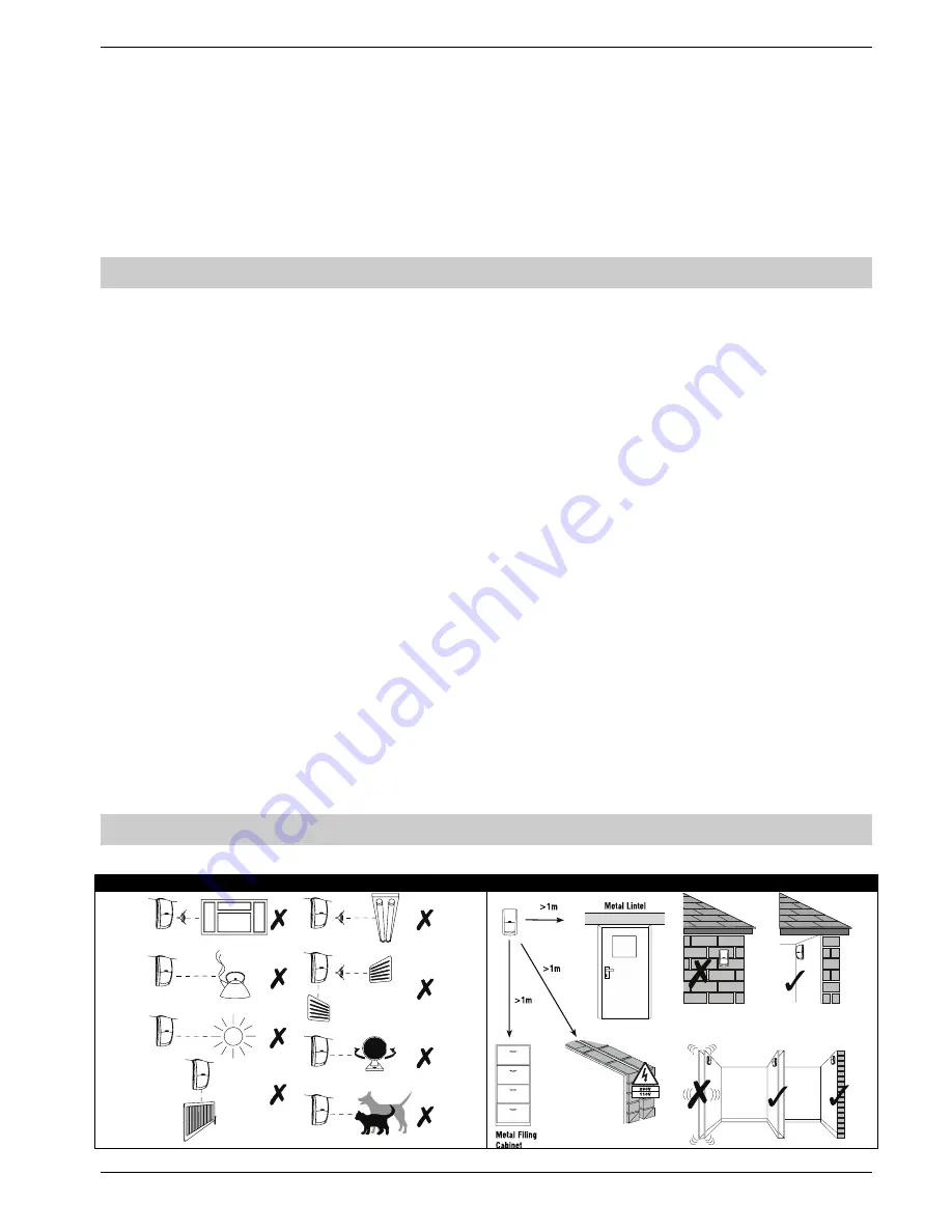
Device Locations 

For all devices, unless specified that they are suitable for the application, please observe the following guidelines. 

Avoid Common False Alarms Causes 

Select the correct location 


Содержание INS626 Premier Elite Ricochet Kits

Страница 1: ...Manual De Usuario Premier 412 816 832 Issue 2 Quick Start Guide Premier Elite Ricochet Enabled Kits INS626...

Страница 2: ...onnecting Keypads Expanders 7 Premier Elite 12 24 48 W Live Front 7 Wiring the Network 7 Keypad Expander Addressing 8 Installing Ricochet devices 8 Learning Devices 8 Device Type 8 Learn method 8 Auto...

Страница 3: ...e found on the enclosed CD Any additional items purchased will also contain detailed instructions Additional Items Required In addition to the contents of the kit you will need the following to comple...

Страница 4: ...EABLE PARTS NO USER ACCESS ONLY connect the mains supply to the mains terminal block NEVER connect the mains supply directly to the PCB ALWAYS refer to National Wiring Regulations when conducting inst...

Страница 5: ...and maintenance System Keypads Should be placed on the entry route if used for arming and disarming Should be placed with the Control Panel if SmartKeys or the App s are used for arming disarming Move...

Страница 6: ...rs code 1234 again i Connect AC Mains 3 The Keypad display will now show Confirm Devices press and again to confirm that all connected keypads and expanders are accounted for 4 The Keypad display will...

Страница 7: ...each network The maximum number of devices that can be connected in total will depend on the control panel fitted Whenever new devices are connected to the networks they must be confirmed onto the sy...

Страница 8: ...ll ensure that they are registered on the receiver or control panel and that Mesh Networks and routing are established correctly SmartKey should be learned after all other devices have been assigned t...

Страница 9: ...stem Use the or to select different zones It is only possible to select Zones which have devices learned The key will cycle between the Learn or Delete options If all devices are deleted from the syst...

Страница 10: ...the LE D Aux functions Using the key at this point allows you to view the group of zones and therefore the expander that the S martKey will use Use the key to select the group of Zones and Expander yo...

Страница 11: ...ite Installation Manual which is on the enclosed CD or available to download from our website Default Engineer Code 00 1234 Default User Code 01 5678 Log Off Engineer Press to log out of the Engineer...

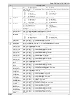
Страница 12: ...for Areas 3 Entry Dly 2 for Areas 8 Part Bell Dly for Areas 4 2nd Entry Dly for Areas 9 Conf PA Timer for Areas 5 Bell Dly for Areas Arming Modes Use to select an area to select arming an mode to acc...

Страница 13: ...33 Poll IP Every 10 Menu Time Out 22 Max Random Time 11 Pulse Period 1 23 Door Strike Time System Config Use to select an option to change the option to accept 00 No Bell Bell on Arm Fail 19 Auto Man...

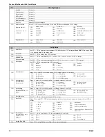
Страница 14: ...4 48 88 168 Use to select keypad to select network to edit to select an area all areas areas A H and I P to accept Areas 640 Use to select keypad to select network to edit to select an area group 1 4...

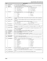
Страница 15: ...Bell Tamper 22 Custom 1 Stage A 39 Com 2 Fault 05 Panel Lid Tamper 23 Custom 1 Stage B 40 Com 1 No Signal 06 Engineer Working 24 Custom 1 Stage AB 41 Com 2 No Signal 07 Confirm Devices 25 Custom 2 Sta...

Страница 16: ...tor Start Test call Press to send test call to the ARC to initiate a call to the remote UDL computer using Call Back numbers 1 2 or 3 Msn Pre Dial Number Press to edit enter call waiting number to acc...

Страница 17: ...Press to edit to enter pad prefix to accept Pad ARC 2 Pri No Press to edit to enter telephone number to accept Pad ARC 2 Sec No Press to edit to enter telephone number to accept Pad ARC 2 Prefix Press...

Страница 18: ...neer Standard Door Strike Local Vacation User Options 1 Press to edit to select an option to change option to accept A Arming R Eng Reset Y Auto YES D Disarming a Local Arming D Disarm First O Omittin...

Страница 19: ...ount Check RKP Status Use to select keypad to select network to display errors tamper to test output to test sounder Check Exp Status Use to select expander to select network to display zones voltage...

Страница 20: ...ry default Master User code is The Master User is always User 01 If the Master User code has been lost or forgotten it can be reprogrammed by the Engineer in this menu Changing the Default Codes To ch...

Страница 21: ...12 W 24 W 48 W 4 Onboard Zones Max 8 16 or 32 wireless device Ricochet enabled receiver onboard Expandable to 12 48 zones via keypads and zone expanders 1 x 4 wire data network standard 7 0 2 alarm ca...

Страница 22: ...The red LED indicates that data is flowing out of the control panel and normally flashes very quickly The green LED indicates that data is flowing into the control panel and normally flashes slowly th...

Страница 23: ...es to all ON 20 Ricochet Firmware Flash Port Connections for flasher interface to update Ricochet receiver firmware factory function only 21 Commission Mode Jumper Fit when learning and placing device...

Страница 24: ...4 4PW England Technical Support UK Customers Tel 08456 300 600 Calls charged at local rate from a BT landline Calls from other networks may vary International Customers Tel 44 1706 233875 Email techsu...

Отзывы: