background image

List of Materials

www.ti.com

16

SNVU552 – March 2017

Submit Documentation Feedback

Copyright © 2017, Texas Instruments Incorporated

Using the LMG1205HBEVM GaN Half-Bridge Power Stage EVM

9

List of Materials

NOTE:

Moisture and other contaminants in the air may provide an environment which allows

dendrite growth under the LMG1205 driver or the GaN MOSFETs on this EVM and lead to
leakage or shorting across high-voltage terminals. The standard assembly of this EVM does
not have underfill material and should be used in low-contaminant conditions. An underfill
material such as Loctite Hysol FP4549Si or Shin-Etsu SMC375X7 should be used in
applications where the board is exposed to moisture.

(1)

Unless otherwise noted, all parts may be substituted with equivalents

(2)

EPC2001 is an acceptable substitute and some EVMs may be assembled using this part number

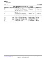
Table 4. LMG1205HBEVM List of Materials

(1)

DESIGNATOR

QTY

VALUE DESCRIPTION

PART NUMBER

MANUFACTURER

PCB1

1

Printed-Circuit Board

SV601338

Any

C1

1

10 µF

CAP, CERM, 10 µF, 25 V, ±10%, X5R, 0805

C2012X5R1E106K125AB

TDK

C2, C20

2

2.2 µF

CAP, CERM, 2.2 µF, 16 V, ±10%, X7R, 0805

C0805C225K4RACTU

Kemet

C3, C4

2

0.1 µF

CAP, CERM, 0.1 µF, 16 V, ±5%, X7R, 0603

0603YC104JAT2A

AVX

C5, C7

2

2.2 µF

CAP, CERM, 2.2 µF, 10 V, ±10%, X7R, 0603

GRM188R71A225KE15D

MuRata

C6

1

100 pF

CAP, CERM, 100 pF, 25 V, ±10%, X7R, 0603

06033C101KAT2A

AVX

C8, C9

2

100 pF

CAP, CERM, 100 pF, 50 V, ±5%, C0G/NP0,
0402

CC0402JRNPO9BN101

Yageo America

C11, C26

2

10 µF

CAP, CERM, 10 µF, 100 V, ±20%, X7R, 2220

22201C106MAT2A

AVX

C12, C13, C24, C25

4

2.2 µF

CAP, CERM, 2.2 µF, 100 V, ±10%, X7R, 1210

C1210C225K1RACTU

Kemet

C14, C15, C16

3

0.1 µF

CAP, CERM, 0.1 µF, 100 V, ±10%, X7R, 0805

C0805C104K1RACTU

Kemet

C17, C27

2

0.1 µF

CAP, CERM, 0.1uF, 25 V, ±10%, X7R, 0603

GRM188R71E104KA01D

MuRata

C18

1

0.1 µF

CAP, CERM, 0.1 µF, 10 V, ±10%, X5R, 0402

C1005X5R1A104K050BA

TDK

C19, C28

2

10 pF

CAP, CERM, 10 pF, 50 V, ±5%, C0G/NP0, 0402 500R07S100JV4T

Johanson Technology

C21

1

1 µF

CAP, CERM, 1 µF, 25 V, ±10%, X5R, 0402

C1005X5R1E105K050BC

TDK

D1, D2

2

40 V

Diode, Schottky, 40 V, 0.03 A, SOD-523

SDM03U40-7

Diodes Inc.

D3, D4

2

Green

LED, Green, SMD

LTST-C170KGKT

Lite-On

H1, H2, H3, H4

4

Machine Screw, Round, #4-40 x 1/4, Nylon,
Philips panhead

NY PMS 440 0025 PH

B&F Fastener Supply

H5, H6, H7, H8

4

Standoff, Hex, 0.5"L #4-40 Nylon

1902C

Keystone

J1

1

Terminal Block, 2.54 mm, 2x1, Brass, TH

OSTVN02A150

On-Shore Technology

J2

1

Header, 100 mil, 4x1, Tin, TH

5-146278-4

TE Connectivity

J3, J4

2

Terminal Block, 2x1, 5.08 mm, TH

282841-2

TE Connectivity

J5

1

Header, 100 mil, 2x1, Gold, TH

TSW-102-07-G-S

Samtec

L1

1

4.7 µH

Inductor, Shielded, Composite, 4.7 µH, 10.5 A,
0.00889

Ω

, SMD

XAL8080-472ME

Coilcraft

Q1, Q2

2

100 V

MOSFET, N-CH, 100 V, 36 A, 4.105x1.632mm

EPC2001C

(2)

EPC

R1, R4

2

47

RES, 47

Ω

, 5%, 0.063 W, 0402

CRCW040247R0JNED

Vishay-Dale

R2, R6

2

10.0 k

RES, 10.0 k

Ω

, 1%, 0.063 W, 0402

CRCW040210K0FKED

Vishay-Dale

R3

1

0

RES, 0

Ω

, 5%, 0.063 W, 0402

CRCW04020000Z0ED

Vishay-Dale

R7

1

0.05

RES, 0.05

Ω

, 1%, 0.1 W, 0603

ERJ-L03KF50MV

Panasonic

R8, R10, R12, R13

4

0

RES, 0, 5%, 0.063 W, 0402

ERJ-2GE0R00X

Panasonic

R11

1

0.005

RES, 0.005, 1%, 2 W, 2512 WIDE

FCSL64R005FER

Ohmite

R15

1

1.0 k

RES, 1.0 k

Ω

, 5%, 0.1 W, 0603

CRCW06031K00JNEA

Vishay-Dale

R16

1

100 k

RES, 100 k, 5%, 0.25 W, 1206

CRCW1206100KJNEA

Vishay-Dale

TP1

1

Test Point, Miniature, Yellow, TH

5004

Keystone

TP2, TP10

2

Black

Test Point, Miniature, Black, TH

5001

Keystone

TP5, TP7

2

Red

Test Point, Miniature, Red, TH

5000

Keystone

Содержание LMG1205HBEVM

Страница 1: ...Using the LMG1205HBEVM User s Guide Literature Number SNVU552 March 2017 ...

Страница 2: ...Typical Applications 7 2 EVM Kit Contents 7 3 Electrical Performance Specifications 7 4 EVM Schematic 8 5 Test Setup 9 5 1 Test Equipment 9 5 2 List of Test Points 10 5 3 List of Terminals 11 5 4 EVM Connections 11 6 Test Procedure 12 6 1 Power Up Procedure 12 6 2 Shutdown Procedure 13 7 Switching Waveforms 13 8 EVM Assembly Drawing and PCB Layout 15 9 List of Materials 16 ...

Страница 3: ...oint TP3 10 9 LO Test Point TP11 10 10 LMG1205HBEVM Test Setup Connections 11 11 Input and Output Waveforms Showing the Dead Time 13 12 Zoom in of the SW Node Running at 50 Duty Cycle 14 13 48 V to 5 V Synchronous Buck Converter Operation Showing Inputs SW Node and VOUT 14 14 LMG1205HBEVM 10 Top Layer and Components 15 15 LMG1205HBEVM 10 Bottom Layer and Components 15 List of Tables 1 LMG1205HBEVM...

Страница 4: ... Qualified observer s must be present anytime circuits are energized Effective barriers and signage must be present in the area where the TI HV EVM and its interface electronics are energized indicating operation of accessible high voltages may be present for the purpose of protecting inadvertent access All interface circuits power supplies evaluation modules instruments meters scopes and other re...

Страница 5: ... designed for professionals who have received the appropriate technical training and is designed to operate from an AC power supply or a high voltage DC supply Please read this user guide and the safety related documents that come with the EVM package before operating this EVM CAUTION Do not leave the EVM powered when unattended WARNING Hot surface Contact may cause burns Do not touch WARNING Hot ...

Страница 6: ...pen loop board with an external PWM signal it is not intended for evaluation of transient response This EVM can be used to evaluate the performance of the LMG1205 in a hard switched converter to sample measurements such as efficiency switching speed and slew rate The EVM features an LMG1205 half bridge driver coupled with two 100 V 7 mΩ GaN FETs in a half bridge configuration The module can delive...

Страница 7: ...onverters for industrial computing and telecom 2 EVM Kit Contents The kit contains the following Safety instructions LMG1205HBEVM PCB assembly 3 Electrical Performance Specifications Table 1 LMG1205HBEVM Electrical Performance Specifications PARAMETER TEST CONDITIONS MIN TYP MAX UNITS VBUS Half bridge input voltage Connected to drain of high side FET 80 V VOUT Half bridge output voltage Connected ...

Страница 8: ...ch 2017 Submit Documentation Feedback Copyright 2017 Texas Instruments Incorporated Using the LMG1205HBEVM GaN Half Bridge Power Stage EVM 4 EVM Schematic Figure 1 shows the schematic of the evaluation module Figure 1 LMG1205HBEVM Schematic ...

Страница 9: ...on this EVM Never leave a powered EVM unattended 5 1 Test Equipment DC Voltage Source capable of supplying the input of the EVM up to 80 V as desired Capable of supplying 10 A and supports current limiting DC Bias Source capable of 5 5 V to 10 V output at up to 500 mA Oscilloscope capable of at least 200 MHz operation 500 MHz preferred using oscilloscope probes with a spring type ground connection...

Страница 10: ...obtained using such a measurement method Table 2 Test Point Functional Descriptions TEST POINT NAME DESCRIPTION TP1 5V_VDD 5 V VDD onboard generated supply TP2 GND GND TP3 HO High side GaN FET gate signal TP4 HB High side Floating Bias Supply TP5 Vbus sense High sense connection for Vbus input voltage TP6 Vbus sense Low sense connection for Vbus input voltage PGND TP7 Vout sense High sense connect...

Страница 11: ...t bus voltage J4 VOUT GaN half bridge output voltage 5 4 EVM Connections Figure 10 shows the required connections for basic operation of the EVM Figure 10 LMG1205HBEVM Test Setup Connections 5 4 1 PWM Input Provide the PWM input using a function generator that is capable of providing the desired switching frequency and duty cycle This function generator output should be connected to the J2 connect...

Страница 12: ...rmed using the LMG1205HBEVM in its default buck converter configuration Never leave a powered EVM unattended for any length of time Also the unit should never be handled while power is applied to it A high voltage power supply with overcurrent protection enabled and or connected in series with a properly rated use is recommended for safe operation Ensure that the electrical characteristic table co...

Страница 13: ... Stage EVM 6 2 Shutdown Procedure Once the desired measurements have been completed shut down the EVM by following these steps 1 Turn off the VBUS supply on J3 2 Disable the function generator 3 Disable the electronic load 4 Disable the VIN bias supply on J1 7 Switching Waveforms VDD 5 V VHS VSS 0 V fSW 5 MHz Figure 11 Input and Output Waveforms Showing the Dead Time ...

Страница 14: ... Texas Instruments Incorporated Using the LMG1205HBEVM GaN Half Bridge Power Stage EVM VIN 12 V fSW 5 MHz No Load Figure 12 Zoom in of the SW Node Running at 50 Duty Cycle VIN 48 V fSW 1 MHz VOUT 5 V No Load Figure 13 48 V to 5 V Synchronous Buck Converter Operation Showing Inputs SW Node and VOUT ...

Страница 15: ...ubmit Documentation Feedback Copyright 2017 Texas Instruments Incorporated Using the LMG1205HBEVM GaN Half Bridge Power Stage EVM 8 EVM Assembly Drawing and PCB Layout Figure 14 LMG1205HBEVM 10 Top Layer and Components Figure 15 LMG1205HBEVM 10 Bottom Layer and Components ...

Страница 16: ...5K1RACTU Kemet C14 C15 C16 3 0 1 µF CAP CERM 0 1 µF 100 V 10 X7R 0805 C0805C104K1RACTU Kemet C17 C27 2 0 1 µF CAP CERM 0 1uF 25 V 10 X7R 0603 GRM188R71E104KA01D MuRata C18 1 0 1 µF CAP CERM 0 1 µF 10 V 10 X5R 0402 C1005X5R1A104K050BA TDK C19 C28 2 10 pF CAP CERM 10 pF 50 V 5 C0G NP0 0402 500R07S100JV4T Johanson Technology C21 1 1 µF CAP CERM 1 µF 25 V 10 X5R 0402 C1005X5R1E105K050BC TDK D1 D2 2 40...

Страница 17: ... FETs YFX0012AHAP DSBGA 12 LMG1205YFXR Texas Instruments 3 U2 1 Triple Schmitt Trigger Inverter DCU0008A VSSOP 8 SN74LVC3G14DCUR Texas Instruments 3 U3 1 1 A Low Dropout CMOS Linear Regulators Stable with Ceramic Output Capacitors 6 pin LLP Pb Free LP38690SD 5 0 NOPB Texas Instruments 3 U4 1 Dual Schmitt Trigger Inverter DBV0006A SOT 6 SN74LVC2G14DBVR Texas Instruments 3 C10 0 22 µF CAP AL 22 µF 2...

Страница 18: ...y set forth above or credit User s account for such EVM TI s liability under this warranty shall be limited to EVMs that are returned during the warranty period to the address designated by TI and that are determined by TI not to conform to such warranty If TI elects to repair or replace such EVM TI shall have a reasonable time to repair such EVM or provide replacements Repaired EVMs shall be warr...

Страница 19: ...the user guide with the maximum permissible gain and required antenna impedance for each antenna type indicated Antenna types not included in this list having a gain greater than the maximum gain indicated for that type are strictly prohibited for use with this device Concernant les EVMs avec antennes détachables Conformément à la réglementation d Industrie Canada le présent émetteur radio peut fo...

Страница 20: ...ed loads Any loads applied outside of the specified output range may also result in unintended and or inaccurate operation and or possible permanent damage to the EVM and or interface electronics Please consult the EVM user guide prior to connecting any load to the EVM output If there is uncertainty as to the load specification please contact a TI field representative During normal operation even ...

Страница 21: ...COST OF REMOVAL OR REINSTALLATION ANCILLARY COSTS TO THE PROCUREMENT OF SUBSTITUTE GOODS OR SERVICES RETESTING OUTSIDE COMPUTER TIME LABOR COSTS LOSS OF GOODWILL LOSS OF PROFITS LOSS OF SAVINGS LOSS OF USE LOSS OF DATA OR BUSINESS INTERRUPTION NO CLAIM SUIT OR ACTION SHALL BE BROUGHT AGAINST TI MORE THAN TWELVE 12 MONTHS AFTER THE EVENT THAT GAVE RISE TO THE CAUSE OF ACTION HAS OCCURRED 8 2 Specif...

Страница 22: ... TI Resource NO OTHER LICENSE EXPRESS OR IMPLIED BY ESTOPPEL OR OTHERWISE TO ANY OTHER TI INTELLECTUAL PROPERTY RIGHT AND NO LICENSE TO ANY TECHNOLOGY OR INTELLECTUAL PROPERTY RIGHT OF TI OR ANY THIRD PARTY IS GRANTED HEREIN including but not limited to any patent right copyright mask work right or other intellectual property right relating to any combination machine or process in which TI product...

Отзывы: