


www.ti.com
Test Setup
11
SNVU552 – March 2017
Submit Documentation Feedback
Copyright © 2017, Texas Instruments Incorporated
Using the LMG1205HBEVM GaN Half-Bridge Power Stage EVM
5.3
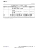
List of Terminals
Table 3. List of Terminals
TERMINAL
NAME
DESCRIPTION
J1
V
IN
LDO bias input for 5-V VDD onboard generated supply
J2
PWM_IN
Function generator input. See
Section 5.4.1
.
J3
V
BUS
GaN half-bridge input bus voltage
J4
V
OUT
GaN half-bridge output voltage
5.4
EVM Connections
Figure 10
shows the required connections for basic operation of the EVM.
Figure 10. LMG1205HBEVM Test Setup Connections
5.4.1
PWM Input
Provide the PWM input using a function generator that is capable of providing the desired switching
frequency and duty cycle. This function generator output should be connected to the J2 connector as
shown in
Figure 10
. The top-most pin (J2-pin1) in this view is the positive input of the PWM supply and
the remaining three pins are connected to GND in the default assembly for the board.


