Texas Instruments ADS5XJ6XEVM Скачать руководство пользователя страница 6

Quick Start Guide

www.ti.com

2.2.2

ADS54J/58J6XEVM Setup

Next, setup the ADS5XJ6XEVM with the following instructions:

1. Connect the included 5-V power supply cable to connector J14 of the EVM. Connect the red wire of

the power cable to +5 VDC ±0.1 VDC of a power supply rated for at least 3 A. Connect the black wire
to the GND terminal of the power supply.

2. Connect the included mini-USB cable to the USB connector J13

3. Set the analog input signal generator for 170 MHz, and about +15 dBm of power

4. Place a narrow passband band-pass filter at the output of the analog signal generator to remove noise

and harmonics from the signal generator

5. Connect the analog input signal generator to the EVM though SMA connector AIN (J1)

2.3

Software Setup Procedure

The software can be opened and configured once the hardware is properly setup.

2.3.1

ADS54J/58J6X GUI Configuration, Mode 0

1. Open the ADS54Jxx GUI by going to

Start Menu

All Programs

Texas Instruments ADCs

ADS54Jxx GUI

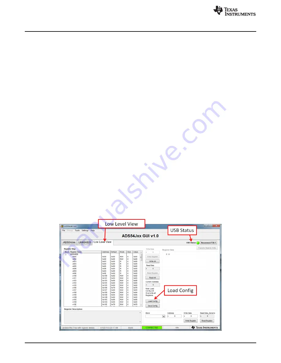
2. Verify that the green USB Status indicator is lit in the top right corner of the GUI. If it is not lit, click the

Reconnect USB

button and check the

USB Status

indicator again. If it is still not lit then verify the EVM

is connected to the computer through the included mini-USB cable.

3. Click on the

Low Level View

tab then click the

Load Config

button.

4. Navigate to “C:\Program Files(86)\Texas Instruments\ADS54Jxx GUI\Configuration Files”, select the

file called “LMK_Config_LMF_4841_491p52_MSPS.cfg”, then click “OK”. This will program the
LMK04828 to provide a 491.52-MHz clock to the ADC.

5. Verify that the LMK04828 PLL is locked by checking that the “PLL2 LOCKED” LED (D3) is lit.

6. Once the LMK04828 PLL is locked, press SW1 (

ADC RESET

) to provide a hardware reset to the ADC.

This switch is located in the middle of the EVM.

7. In the

Low Level View

tab, click

Load Config

. Select the file called “ADS5xJ6x_2x_Fs_4_mode_0.cfg”

and click "OK". The ADS5XJ6XEVM is now configured for a fixed frequency Fs/4 complex digital mixer
and decimate by 2 digital filter mode using 4 JESD204B lanes.

Figure 3. ADS54Jxx GUI Low Level View Tab

6

ADS5XJ6X Evaluation Module

SLAU641D – June 2015 – Revised January 2016

Submit Documentation Feedback

Copyright © 2015–2016, Texas Instruments Incorporated

Содержание ADS5XJ6XEVM

Страница 1: ...tup 5 3 ADS54Jxx GUI Low Level View Tab 6 4 HSDC Pro GUI Main Panel 7 5 Channel 1 Data Capture Results from Quick Start Procedure 8 6 Channel 1 Data Capture Results in Bypass Mode 9 7 ADS54Jxx GUI 12...

Страница 2: ...uation The ADS5XJ6XEVM was also designed to work with many of the development kits from leading FPGA vendors that contain an FMC connector 1 1 Required Hardware The following equipment is included in...

Страница 3: ...es the locations of the EVM features Figure 1 EVM Feature Locations 1 4 References The following links provide convenient references ADS5XJ6XEVM software schematics layout BOM available at www ti com...

Страница 4: ...ADS5XJ6XEVM It must be used to properly configure the devices on the EVM 1 Download the ADS54Jxx GUI from the TI website The References section of this document contains link to find the software on...

Страница 5: ...The rest of this section will describe the hardware setup steps Figure 2 Quick Start Test Setup 2 2 1 TSW14J56EVM Setup First setup the TSW14J56EVM with following the instructions 1 Connect the ADS54J...

Страница 6: ...is lit in the top right corner of the GUI If it is not lit click the Reconnect USB button and check the USB Status indicator again If it is still not lit then verify the EVM is connected to the compu...

Страница 7: ...6 This will take about 3 seconds 7 Enter 245 76M into the ADC Output Data Rate field at the bottom left corner then click outside this box or press return on the PC keyboard 8 The GUI will display the...

Страница 8: ...y In the ADS54Jxx GUI click on the Low Level View tab then click the Load Config button Navigate to C Program Files 86 Texas Instruments ADS54Jxx GUI Configuration Files select the file called LMK_Con...

Страница 9: ...ration files Click OK Click the Instrument Options menu at the top of HSDC Pro and select Reset Board Make sure the display mode is set to Real FFT Click Capture in HSDC Pro to capture data from the A...

Страница 10: ...Serial Device is recognized when the EVM is connected to the PC Verify that the green USB Status LED light in the top right corner of the GUI is lit If it is not lit press the Reconnect FTDI button Tr...

Страница 11: ...d better SNR results The clock and analog inputs must be frequency locked such as through 10 MHz references in order to achieve coherency 3 3 HSDC Pro Settings HSDC Pro has some settings that can help...

Страница 12: ...l View tab to load configuration files LMK04828 Enables control of many of the LMK04828 features Configuration files can be used to setup the LMK04828 in known working configurations however this tab...

Страница 13: ...n in the Register Map with the values shown in the Register Map log The log can be viewed by double left clicking in the bottom left status bar of this page Read Register Button Read from the register...

Страница 14: ...o provide the device clock to the TSW14J56 and the SYSREF signals to both boards This option will provide the best performance as long as the clock source has better phase noise performance than the L...

Страница 15: ...CXO The LMK04828 is used as a clock generator using the onboard 122 88 MHz VCXO JP2 must be shorted to turn on the onboard VCXO The internal PLLs of the LMK04828 can be used with the onboard VCXO to g...

Страница 16: ...tion described in Table 8 Table 8 Connector Description Connector Description J1 Channel A analog input J17 Channel B analog input J18 Channel C analog input J5 Channel D analog input J6 External ADC...

Страница 17: ...ecember 2015 to D Revision Page Changed first bullet in the not included items list in the Required Hardware section to two 5 V power supplies 2 Changed Quick Start Test Setup image 5 Changed content...

Страница 18: ...ing the warranty period to the address designated by TI and that are determined by TI not to conform to such warranty If TI elects to repair or replace such EVM TI shall have a reasonable time to repa...

Страница 19: ...transmitter has been approved by Industry Canada to operate with the antenna types listed in the user guide with the maximum permissible gain and required antenna impedance for each antenna type indic...

Страница 20: ...ified allowable ranges some circuit components may have elevated case temperatures These components include but are not limited to linear regulators switching transistors pass transistors current sens...

Страница 21: ...REMOVAL OR REINSTALLATION ANCILLARY COSTS TO THE PROCUREMENT OF SUBSTITUTE GOODS OR SERVICES RETESTING OUTSIDE COMPUTER TIME LABOR COSTS LOSS OF GOODWILL LOSS OF PROFITS LOSS OF SAVINGS LOSS OF USE L...

Страница 22: ...sponsible for compliance with all legal regulatory and safety related requirements concerning its products and any use of TI components in its applications notwithstanding any applications related inf...

Отзывы: