


TPMC810 User Manual Issue 2.0.0
Page 16 of 22
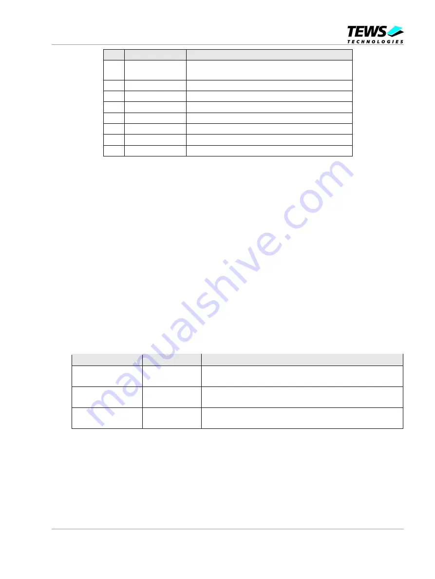
Bit
Symbol
Description
7
CAN Mode
0 : BasicCAN Mode
1 : PeliCAN Mode
6
CBP
1 : Bypass input comparator, use RX0 only
5
RXINTEN
0 : Disable interrupts on TX1 output
4
-
0
3
clock off
1 : Disable clock output (not used)
2
CD.2
0
1
CD.1
0
0
CD.0
0
Table 5-2 : Clock Divider Register (CDR; 0x1F)
5.1.4 Integrated Data Buffer
The data to be transmitted on the CAN bus is loaded into the memory area of the SJA1000, called
“Transmit Buffer”. The data received from the CAN bus is stored in the memory area of the SJA1000,
called “Receive Buffer”. These buffers contain 2, 3 or 5 bytes for the identifier and frame information
(dependent on mode and frame type) and up to 8 data bytes.
BasicCAN Mode: The buffers are 10 bytes deep (see figure “Rx- and Tx-buffer in BasicCAN Mode”).
o
2 identifier bytes
o
up to 8 data bytes
PeliCAN Mode: The buffers are 13 bytes deep (see figure “Rx- and Tx-buffer in PeliCAN Mode”).
o
1 byte for frame information
o
2 or 4 identifier bytes (Standard Frame or Extended Frame)
o
up to 8 data bytes
Address
Name
Composition and Remarks
Tx-buffer: 0x0A
Rx-buffer: 0x14
Identifier Byte 1
8 Identifier bits
Tx-buffer: 0x0B
Rx-buffer: 0x15
Identifier Byte 2
3 Identifier bits, 1 Remote Transmission Request bit,
4 bits for the Data Length Code, indicating the amount of data bytes
Tx-buffer: 0x0C-0x13
Rx-buffer: 0x16-0x1D
Data Byte 1 - 8
Up to 8 data bytes as indicated by the Data Length Code
Table 5-3 : Rx- and Tx-buffer in BasicCAN Mode


