


February 2022
Service Manual
Mast Components
Part No. 1314708GT
GRC
™
69
25 Attach a lifting strap from an overhead
supporting device to the mast assembly and
carefully rotate the mast 180°. Set the mast
assembly onto the work table and secure the
mast to the table.
Crushing hazard. The mast
assembly will fall if it is not
properly supported by an
overhead supporting device.
Note: During installation, the lifting strap will need
to be adjusted for proper balancing.
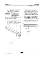
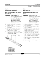
26 Using Illustration 10 as a guide, stagger the
mast assembly.
27 Slide the lower, inner corner wear pads
between mast sections 1 and 2, 2 and 3, and,
3 and 4. Align the holes on the wear pads to
the rivet holes on the lower half of mast
sections 2, 3 and 4. Secure the wear pads
into place using the appropriate rivets.
Illustration 10
1 mast number 4
2 rivet
3 wear pads
4 limit switch
5 mast number 1
6 mast number 2
7 mast number 3
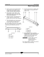
28 Carefully collapse the mast assembly.
29 Attach a lifting strap from an overhead
supporting device to the lift cylinder. Working
from the lower half of the mast assembly,
carefully slide the lift cylinder into the mast
assembly, aligning the rod ends of the
cylinder, to the cylinder mast mounting
brackets at the upper half of the mast
assembly.
Crushing hazard. The lift
cylinder could become
unbalanced and fall if not
properly supported and secured
to the lifting device.
Note: During installation, the lifting strap will need
to be adjusted for proper balancing.
30 Working at the upper half of the mast
assembly, install the lift cylinder nylock nuts
onto the lift cylinder. Torque to 300 ft-lbs / 406
Nm.
31 Working from the lower half of the mast
assembly, install the mast cylinder pin into the
mounting holes of the number 1 mast and the
lift cylinder.
32 Install the hair pin clips onto each side of the
mast cylinder pin.
33 Install the lift cylinder retaining bolt onto the
lower cylinder block. Do not over tighten the
bolt.
34 Using the appropriate fasteners, install the
limit switch assembly onto the lower half of
the mast assembly. Do not over tighten the
fasteners. Refer to Illustration 10.
35 Connect the hydraulic hose to the lift cylinder.
Note: When removing a hose assembly or fitting,
the O-ring (if equipped) on the fitting and/or hose
end must be replaced. All connections must be
torqued to specification during installation. Refer to
Specifications,
Hydraulic Hose and Fitting Torque
Specifications.
Содержание Genie GRC-12
Страница 110: ...Service Manual February 2022 Wiring Diagram Ground and Platform Controls 98 GRC Part No 1314708GT...
Страница 113: ...February 2022 Service Manual 101 Electrical Schematic GRC Options...
Страница 115: ...February 2022 Service Manual 103 Electrical Schematic GRC from GRC11 1000 to GRC11 1078...
Страница 118: ...Service Manual February 2022 106 Electrical Schematic GRC from GRC11 1000 to GRC11 1078...
Страница 119: ...February 2022 Service Manual 107 Electrical Schematic GRC from GRC11 1079 to GRC14 1780...
Страница 122: ...Service Manual February 2022 110 Electrical Schematic GRC from GRC11 1079 to GRC14 1780...
Страница 123: ...February 2022 Service Manual 111 Electrical Schematic GRC from GRC14 1781 to GRC15 2343...
Страница 126: ...Service Manual February 2022 114 Electrical Schematic GRC from GRC15 2344 to GRC16P 2481...
Страница 127: ...February 2022 Service Manual 115 Electrical Schematic GRC from GRC16P 2482 to GRC16P 2562...
Страница 130: ...Service Manual February 2022 118 Electrical Schematic GRC from GRC16P 2563 to GRCP 5999...
Страница 131: ...February 2022 Service Manual 119 Hydraulic Schematic GRC from GRC11 1000 to GRC12 1168...
Страница 135: ......