OPERATION
2Ć9
186E MM160 (6–94)
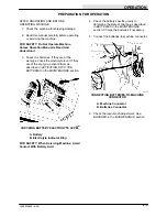
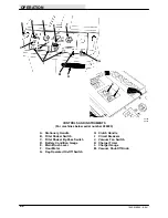
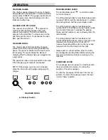
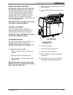
MAIN BRUSH LEVER
The main brush lever controls the position of the
main brush. To raise the main brush, pull the lever
up, to the right and back into the
(Main
Brush Up) position (lower groove). To lower the
main brush on smooth surfaces, push the lever
forward and pull it back into the
(Main Brush
Down) position (top groove). To lower the main
brush on uneven surfaces, push the lever forward,
to the left, and release it into the
(Main
Brush Free-Float) position.
When parking the machine, always raise the
brush to prevent the bristles from taking a set.
To increase main brush contact with the floor, turn
the main brush lever to the left. To decrease main
brush contact with the floor, turn the lever to the
right.
A
E
C
D
B
03134
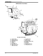
MAIN BRUSH LEVER
A. Main Brush Lever
B. Instrument Panel
C. (Main Brush Up) Position
D. (Main Brush Down) Position
E. (Main Brush Free-Float) Position
HOUR METER
The hour meter records the number of hours the
machine has operated. This information is useful
in determining when to service the machine.
KEY-OPERATED ON-OFF SWITCH
The key-operated on-off switch
has two
positions: off and on. To turn the machine on, turn
the key fully to the right to the on position. To turn
off the machine, turn the key to the left to the off
position.
CIRCUIT BREAKERS AND FUSES
Circuit breakers are resetable circuit protection
devices designed to stop the flow of current in the
event of a circuit overload. Once tripped, circuit
breakers must be manually reset by pressing the
circuit breaker button in. If the overload which
caused the circuit breaker to trip is still present in
the circuit, the circuit breaker will continue to stop
current flow until the overload is corrected.
Fuses are a one-time circuit protection device
designed to stop the flow of current in the event of
a circuit overload. Never substitute higher value
fuses than those specified in this manual.
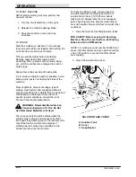
The circuit breakers are located on the instrument
panel. The fuse is located behind the hopper on
the main frame.
The following chart shows the various circuit
breakers and the electrical components they
protect.
PROTECTIVE
DEVICE
RATING
CIRCUIT PROTECTED
CB–1
15 A
Shaker Motor
CB–2
15 A
Hour Meter,
Thermo-Sentry
CB–3
17.5 A
Vacuum Fan Motor
FU–1
60 A
Motor
VACUUM FAN SWITCH
The vacuum fan switch
controls the vacuum
fan. To start the vacuum fan, flip the switch toggle
up. To stop the fan, flip the switch toggle down.
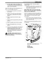
CHARGER TIMER
The charger timer controls the battery charger on
machines below serial number 006823. To start
the battery charger, turn the timer knob to the
number of hours you wish to charge the batteries.
The timer will automatically stop the charger.
WARNING: Batteries Emit Hydrogen
Gas. Explosion Or Fire Can Result.
Keep Sparks And Open Flame Away. Keep
Covers Open When Charging.
Содержание 186E
Страница 1: ...186E MM160 Rev 12 12 95 Operator Manual ...
Страница 8: ...GENERAL INFORMATION 186E MM160 6 94 vi ...
Страница 10: ...SPECIFICATIONS 186E MM160 6 94 1Ć2 ...
Страница 14: ...OPERATION 186E MM160 6 94 2Ć2 ...
Страница 48: ...MAINTENANCE 186E MM160 6 94 3Ć12 ELECTRICAL SCHEMATIC 186E For machines below serial number 004369 03130 ...
Страница 49: ...MAINTENANCE 3Ć13 186E MM160 6 94 ELECTRICAL SCHEMATIC 186E For machines serial number 004369 to 006822 03130 ...
Страница 50: ...MAINTENANCE 186E MM160 6 94 3Ć14 ELECTRICAL SCHEMATIC 186E For machines serial number 006823 and above 03130 ...
Страница 51: ...MAINTENANCE 3Ć15 186E MM160 6 94 ELECTRICAL SCHEMATIC 186EE For machines below serial number 006823 03095 ...
Страница 52: ...MAINTENANCE 186E MM160 6 94 3Ć16 ELECTRICAL SCHEMATIC 186EE For machines serial number 006823 and above 03095 ...
Страница 84: ...APPENDIX 186E MM160 6 94 4Ć2 ...
Страница 86: ...APPENDIX 186E MM160 6 94 4Ć4 ...


