background image


Snappi System User Manual 


Document No: 053-05 v38 

Page 10 of 76 

June 2022 

Snappi System User Manual.doc


Option 1

 (see example below of what the label looks like): 

The first serial number will be on the brake bar between the 
two rear wheels. The label is a large white label with lots of 
information on including what the product actually is e.g. size 
1 Snappi chassis. On the label will be the letters SN (short 
for serial number) and then some numbers after this. Please 
kindly advise what this number is. The second white label is 
underneath the seat so you will need to look underneath the 

buggy. Again, this will have lots of information on and you want the numbers after the 
letters SN. 
 

Option 2

There are two serial numbers. TEN/SC and then four numbers and TEN/SS and then four 
numbers. The SC one is located on the chassis itself (on the bar between the two rear 
wheels and will start with TEN/SC followed by four numbers e.g. TEN/SC1234) and the SS 
one is located on the seat (when the seat is in the buggy, where the back of the seat joins 
the base of the seat and will start with TEN/SS followed by four numbers e.g. 
TEN/SS1234). 


4:  Preparing the wheelbase for use 
 
WARNING: 
When opening or folding the wheelbase, ensure that you hold the frame so that you 
avoid any danger of catching your fingers in moving parts. 
 
Keep children clear of the wheelbase during opening and folding. 
 
 
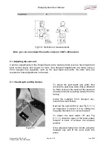
4.1.1 Unfolding the Frame (original locks) 


Standing  at  back  of  the  wheelbase, 
place  your  foot  on  the  rear  cross 
member  X  (see  Fig  4.1.1.1)  and  lift 
handle labelled Y as far as it will move. 
 
This will open the frame. 

Fig 4.1.1.1 


Содержание Snappi Pushchair

Страница 1: ...hair USER MANUAL ALL SIZES IMPORTANT Please read these instructions carefully before using the Snappi System In addition we have a YouTube channel with a series of How to guides to provide a visual demonstration Please note that these videos are not a substitute for reading your manual QR code link to video guides ...

Страница 2: ...Snappi System User Manual Document No 053 05 v38 Page 2 of 76 June 2022 Snappi System User Manual doc Fig 0 1 Complete Pushchair size 1 shown Snappi Seat Unit Snappi Chassis ...

Страница 3: ...pi System User Manual doc Fig 0 2 Chassis size 1 shown Fig 0 3 Seat Unit Size 1 shown Brake Bar Push Handle Adjustor Tilt Lever Spring Loaded Locking Slider Adjustable Back Hip Guides Side Pads Interface Playtray Mountings Footrest Adjustable Base Knee Angle Adjustors Hip Belt ...

Страница 4: ...Snappi System User Manual Document No 053 05 v38 Page 4 of 76 June 2022 Snappi System User Manual doc Fig 0 4 Folded System Complete size 1 only Fig 0 5 Folded System 2 part fold all models ...

Страница 5: ...ing the Tilt In Space facility 21 4 5 Folding as a complete system size 1 only 22 4 6 Folding as a 2 part system all models 22 5 Setting up the seat unit 23 24 5 1 Adjusting the seat unit 24 5 1 1 Seat Depth and Hip Guides 24 25 5 1 2 Footrest Depth and Knee Angle Adjustment 25 5 1 3 Back height and recline angle adjustment 26 5 1 4 Lateral Supports Optional 27 28 5 2 Fitting and Removing the Cove...

Страница 6: ... pushing 65 66 8 1 Pushing 69 70 8 2 Brakes 67 8 3 Comfort 67 8 4 Lifting and general safety 67 9 Cleaning 67 9 1 Buggy and seat unit 67 68 9 2 Seat Cover 68 9 3 Pelvic strap harnessing 68 10 Maintenance 68 10 1 Routine maintenance 68 69 10 2 Six monthly maintenance 69 10 3 Additional workshop maintenance 69 70 11 Oxygen Cylinder 70 12 Warranty Product Life Service Life Reuse 70 12 1 Warranty 70 7...

Страница 7: ...e in accordance with ISO 7176 19 please see section 13 Transporting the Wheelbase for full instructions The pushchair is available in 3 sizes size 1 with minimiser size 1 and size 2 A wide range of accessories are available for the Snappi pushchair to enable customisation to an individual s specific requirements Risks Associated with Use and Contraindications If used properly risks can be eliminat...

Страница 8: ... 7 5kg 12 5kg Maximum Carry Weight 40 55kg 40 55kg 40 55kg IMPORTANT Knee angle adjustable in 15 increments Maximum carry weight is defined as the user weight plus any accessories equipment which may be fitted or carried on the chassis The weight of the Snappi seat has been taken into account with these weights and you do not need to make any deduction for the Snappi Seat Warning Never exceed the ...

Страница 9: ...the seat first then the wheelbase Do not attempt to lift both parts out together The carton should contain the following items Item Component QTY Yes No 1 Wheelbase 1 2 Seat Unit 1 3 User Manual 1 4 5mm Alan key 1 Please note accessories such as lateral supports or harnessing that were ordered at the same time as the pushchair will be included in either the main package or a separate carton IMPORT...

Страница 10: ...re are two serial numbers TEN SC and then four numbers and TEN SS and then four numbers The SC one is located on the chassis itself on the bar between the two rear wheels and will start with TEN SC followed by four numbers e g TEN SC1234 and the SS one is located on the seat when the seat is in the buggy where the back of the seat joins the base of the seat and will start with TEN SS followed by f...

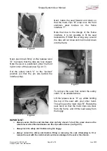
Страница 11: ...s in and slide the 2 locking pieces down over the lower tube sections See Fig 4 1 1 3 Fig 4 1 1 3 Fig 4 1 1 4 The pins will spring through the holes in the sliders and hold them in place see Fig 4 1 1 4 WARNING If the locking sliders are not in the correct position or the spring pins do not protrude thereby allowing the locking clips to move back up the frame then the frame may collapse in use Fol...

Страница 12: ...g against the locking springs Once fully open the frame locks will snap shut over the front frame securing the frame in the open position Always check that both locks are fully closed In the locked position the guide bolt B will be sat in the top of the slot A on the side of the slider as shown see Fig 4 1 2 3 If there is any slot visible above the guide bolt push the lock down by hand until it wi...

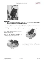
Страница 13: ...lease note you may find it easier to use your hand to release the brake If operating the brake by hand always hold the brake by the raised section in the middle of the bar Important Always put the brake on when placing the child in or taking them out of the pushchair Do not leave the brake on when the pushchair is not in use as this will damage the rear wheels Fig 4 2 2 WARNING The brake mechanism...

Страница 14: ...4 2 4 Right The brake in the fully locked position Fig 4 2 4 Fig 4 2 5 To release the pin brake hold the pushchair and place your foot underneath the brake bar as shown see Fig 4 2 5 left Lift the bar as far as it will move to ensure the pins are clear of the locking rings Warning When operating the brake mechanism ensure that you always keep a firm hold of the pushchair and keep your hands well a...

Страница 15: ...e the tyres 4 2D Push Handle Mounted Attendant Brakes Hub optional upgrade Hub brakes are available only as a factory fitted option The following instructions detail how to operate the hub brakes NOTE The hub brake upgrade means the standard foot operated brake is removed and is not available on pushchairs fitted with hub brakes The hub brakes include a locking function that provides the same func...

Страница 16: ... Always ensure that the pushchair is on level ground to prevent risk of injury to the occupant and help prevent tipping Do not attempt to push the pushchair when the brake is locked off Doing so may damage the brake mechanism If you need to slow down the momentum of your pushchair i e when on a hill you must not lock off the brake rather you must keep your finger pressed on the automatic lock as s...

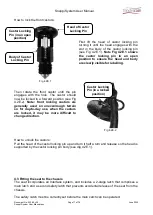
Страница 17: ...g castors are generally used on uneven rough terrain so for day to day use when the castors are locked it may be more difficult to change direction Fig 4 2E 2 How to unlock the castors Pull the head of the castor locking pin up and turn it half a turn and release so the head is supported by the castor locking pin body see dig 4 2E 1 4 3 Fitting the seat to the chassis The seat incorporates an Inte...

Страница 18: ... opposite direction so that pin Y is fully protruded and sits behind the interface main catch B see fig 4 3 3 on next page Fig 4 3 2 Safety Catch unlocked Important When fitting or removing the seat the carer parent must first ensure that the safety catch pin is set in the unlocked position It will not be possible to fit or remove the seat if the latch is locked and attempting to do so may cause d...

Страница 19: ...ks B Seat Interface Main Clips C Seat Interface Safety Catch D Seat Interface Release Handle E Frame interface rear bushings F Frame interface front bushings Ensure that the safety catch C has been unlocked see instructions on previous page Holding the seat as shown tilt it back and locate the 2 rear hooks A on the back of the interface over the stainless steel bushings on the back of the frame in...

Страница 20: ...Set the safety catch C to the Locked position so that the pin sits behind the interface clip Fig 4 3 7 Fig 4 3 8 To remove the seat first unlock the safety catch C as detailed above Lift the release lever D up whilst holding the top of the seat with your other hand This will open the main clips B Rotate the seat back so that the main clips are clear from the frame and lift the seat away from the b...

Страница 21: ...ism place your hand over the push handle adjustor and lift the lever L see Fig 4 4 1 as shown This will open the gas strut and tilt the seat Note The speed of tilt can be controlled by varying the pressure applied at lever L Use your other hand to support seat as it tilts Fig 4 4 2 Fig 4 4 3 To reset the tilt mechanism hold down lever L and push down firmly on the front of the seat as shown see Fi...

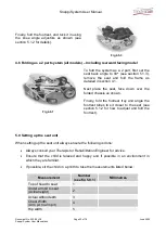
Страница 22: ...when tilting as the gas springs can be quick to operate If the seat is not supported is may move swiftly and could cause the occupant distress 4 5 Folding as a complete system size 1 only Not suitable for rearward facing model First set the seat to full tilt in space as detailed in section 4 4 Next fold the chassis as described in section 4 1 without removing the seat Fig 4 5 1 Fig 4 5 2 Next set ...

Страница 23: ...er the folded chassis as shown Finally fold the footrest tray and angle the footrest tubes to sit closer to the seat see section 5 1 2 for how to adjust and fold the footrest 5 0 Setting up the seat unit When setting up the seat unit always ensure the following is done Always consult your Therapist or Rehabilitation Engineer for advice Ensure that the child is relaxed and happy and if possible in ...

Страница 24: ...equired to make adjustments to the seat 5 1 1 Seat Depth and Hip Guides Fig 5 1 1 1 To adjust the seat depth and width first remove the seat base cover this is attached by Hook loop in the centre of the seat and is easily removed by pulling it away from the frame Using the supplied 5mm hexagon key loosen the 4 seat fixings Next set the seat width A see Fig 5 1 1 1 as measured in section 5 0 by sli...

Страница 25: ... the 5mm hexagon key as shown see Fig 5 1 2 1 On some size 2 models wing nuts may be fitted in place of bolts and therefore the adjustment can be made by hand Slide the footrest up or down the guide tubes to the required height as measured in section 5 0 Once set lock the position by tightening the 2 fixing bolts wing nuts To adjust the knee angle press in the angle adjustors on both sides of the ...

Страница 26: ... the back height you may need to remove any lateral trunk supports and or the top straps of any chest harnessing To adjust the back angle grip the adjustment lever and lift it up whilst holding the rear cross bar with your thumb See Fig 5 1 3 1 To recline the seat pull the top of the seat backwards to the required angle and release the adjustment lever For seats fitted with a dynamic gas strut the...

Страница 27: ... M8 coach bolts and two 30mm hand wheels per bracket see Figs 5 1 4 1and 5 1 4 2 To fit the laterals The laterals are fitted by securing with coach bolts and hand wheels through the mounting slots H see Fig 5 1 4 3 on the back of the seat unit Fig 5 1 4 3 Fig 5 1 4 4 The lateral bracket must be fed through the slot in the cover see Fig 5 1 4 4 Next insert the 2 coach bolts through the bracket and ...

Страница 28: ...the mounting slots H see fig 5 1 4 3 There is a partition in the slots between the upper and lower back plates To achieve the full adjustment range the laterals need to be fitted in the appropriate section of the slots Fig 5 1 4 5 5 2 Fitting and Removing The Covers Fig 5 2 1 To remove the seat pad Simply lift the front edge of the seat pad to separate it from the Hook loop strip on the base To re...

Страница 29: ...t Next unhook the top of the back pad from the seat and then un tuck the material from around the bottom of the seat back plates to release the cover Fig 5 2 4 5 3 Fitting a Headrest Pad or Lateral Head Supports optional Fig 5 3 1 To fit a headrest pad There are three types of one piece headrest available standard extra recess Fig 5 3 1 and occipital roll however these can all be fitted to the sea...

Страница 30: ...ig 5 3 5 The lateral head supports are supplied with two M8 coach bolts and two 30mm hand wheels per bracket see Fig 5 3 5 To fit the head supports The lateral head supports are fitted by securing with coach bolts and hand wheels through the mounting slots I see Fig 5 3 6 on the back of the seat unit The position of the laterals can be adjusted laterally by loosening the hand wheels and sliding th...

Страница 31: ... old style Snappi which can be distinguished by having only one cam lock buckle on each side Open the cam lock buckles these are located on the bottom left and right corners of the seat base Feed the webbing of the strap through the cam lock See Fig 5 4 3 Fig 5 4 3 Fig 5 4 4 Adjust the length of the pelvic strap by pulling the webbing through the cam buckle until it is at the required length Fig 5...

Страница 32: ...g through the cam buckle until it is at the required length Fig 5 4 6 Once adjusted lock the buckles on both sides of the seat to secure the strap Important The pelvic strap must be located as low down over the hips as possible It must not cross the stomach of the passenger To fit the 4 point pelvic strap to the new style Snappi which has 3 cam buckles on each side Open the middle and front cam lo...

Страница 33: ...the seat See Fig 5 5 3 The slot that should be used will be determined by the size of the child For larger children the slot closest to the front of the seat will probably be more suitable whilst for smaller children the second slot in would most likely be appropriate Please note you may need to move the 3 bar slider down the strap Fig 5 5 2 Fig 5 5 3 The pelvic strap or lap belt of the H belt har...

Страница 34: ... for the user Fig 5 6 1 Alternatively an H Belt hanress is available which comprises 4 padded straps that join together with a quick release buckle to provide easy open and release of the harness Important The harnesses fitted are for postural support only and must not be used as a vehicle harness Please see section 13 for transport instructions Fig 5 6 2 Fig 5 6 3 If the Snappi was not originally...

Страница 35: ...ness is at the desired height and then close the cam buckles to secure the webbing Fig 5 6 7 To fit the cam buckles thread the supplied bolts and washers through the holes in the webbing straps and screw through the fixing holes in the bar on the rear of the seat Fig 5 6 4 For a size 1 Snappi we recommend using the inner holes and for the size 2 Snappi the outer holes Tighten using a 3mm Allen Key...

Страница 36: ...uides and down through the cam buckles at the rear of the side plate Set at the desired length and close cam buckle to secure webbing Fig 5 6 8 OR Fig 5 6 8 On Snappi Pushchairs with 1 side cam buckle Thread the bottom straps through the gap at each side between the back upholstery and hip guides Twist the cam catch to one side so you can access the top of the bolt where you will need to attach th...

Страница 37: ...t the pelvic strap is secure and adjusted correctly 3 Check that the cover is correctly fitted 4 Check that the seat unit is located and locked correctly in the chassis 5 Ensure the safety catch is locked 6 Position the child correctly in the seat and assess the child s posture if the child s posture appears to have changed remove the child and compare the support positions to the measurements tak...

Страница 38: ...elp with loading of bulky items To expand the basket simply peel apart the Hook loop at the back to release the extra material Important Always check that the shopping basket is securely fitted before use The maximum carrying load for the shopping basket is 3kg Always ensure that the total load of the occupant and accessories does not exceed the maximum carry limit stated for the pushchair see sec...

Страница 39: ...nt cross bar Finally turn the front catch B 90 degrees so it sits under the front cross bar this catch may be quite tight Fig 6 2 1 Fig 6 2 2 To remove the tray unlock catch B lift up and remove the tray from the chassis Important Always ensure the equipment carrying tray is securely fitted before use and the o2 if using o2 tray is securely fastened If you are carrying oxygen you must either use t...

Страница 40: ...fit over the frame Position the mounting onto the upper frame tube see fig 5 3 4 below Adjust the angle of the clip so that it is vertical Fig 6 3 3 Fig 6 3 4 When in the desired position retighten the screw to lock it onto the frame Finally clip the umbrella section back onto the mounting by pushing the 2 halves of the clip back together and open the umbrella If a different angle is needed simply...

Страница 41: ...unhood and rainshield are two separate items To fit the rainshield you must first fit the sunhood The rainshield fits the same way regardless of what sunhood fixings you have New Style Sunhood Fixings Fig 1 Fig 1 left shows the back of your Snappi seat The two white arrows are pointing to the sunhood receiver brackets on the back of the chair These brackets are fitted to all Snappi pushchair as st...

Страница 42: ...he button clips facing you Pressing both button clips simply slide the hood down into the sunhood brackets to the position shown in Fig 4 right Fig 4 Fig 5 There are 2 positions you can lock the button hole into Fig 4 shows the button hole fitted in the top position However if needed the hood can be dropped to the lower hole position You can see both hole positions in Fig 5 left To do this push in...

Страница 43: ...t the hood to the position you desire then tighten the thumb screws to hold the hood securely in place Each time you wish to change the angle of the hood you must first loosen the thumb screws adjust the angle as desired and then ensure that you retighten the screws to prevent them falling off Removing The Sunhood To remove the hood first unfasten the hook and loop strap shown in Fig 6 and then pr...

Страница 44: ...with its tubes folded in as shown in Fig 2 right Fig 2 Fig 3 Before you can fit the sunhood to the buggy you need to first loosen the thumb screws on either side of the hood and unfold both sunhood tubes so they face the bottom of the hood see Fig 4 right There will be two thumb screws one on either side of the sunhood see Fig 3 left Fig 4 Sunhood Tube Thumb Screw ...

Страница 45: ...for the occupant The push on clips can be attached anywhere on the welded support bars The central strap is designed to be an additional security measure to keep the hood attached Once you have clipped the sunhood onto the welded supported bars the straps should be threaded behind the bars and secured with the attached cam buckle See Fig 6 We would recommend you keep the strap fastened at all time...

Страница 46: ...ust first loosen the thumb screws adjust the angle as desired and then ensure that you retighten the screws to prevent them falling off Rainshield Instructions To fit the plastic rainshield unfold it from its packaging and place over the sunhood with the hook loop rainshield flap facing the front i e world as opposed to occupant facing The sunhood angle needs to be set to match the seemlines to th...

Страница 47: ...Fig 11 Important Points When Using The Sunhood Rainshield In warm conditions e g inside building warm days etc ensure you undo the hook loop flap at the front of the rain shield and fold it back to prevent the occupant of the pushchair from overheating On some occasions undoing the flap may not be sufficient to keep the occupant cool as such you may need to completely remove the rainshield We do n...

Страница 48: ...found in your Snappi User Manual Although the sunhood is made of showerproof black fabric it is still necessary to use the transparent rainshield to protect the occupant from the rain If you remove the screws from the hood for any reason please ensure that you screw them back on to the hood through the hole in the fabric Do not try to stretch the hole over the screw as you may damage the material ...

Страница 49: ...truding through the adjustors see fig 6 4c 3 Remove the coach bolt taking note of its position in relation to the other parts Fig 6 4c 4 Fig 6 4c 5 The adjustor bracket should now be free remove the frame mounting bars from the middle of the adjustor as shown see Fig 6 4c 5 Next slide the other 2 parts of the adjustor off the end of the sun hood frame bars Fig 6 4c 6 ...

Страница 50: ...g 6 4c 7 To wash the cover wash on its own at 30 degrees on a synthetic cycle For brightly coloured fabrics include a colour catcher to help prevent the colour running Do not dry clean or bleach the cover Allow the cover to dry naturally Do not iron or tumble dry When the cover is completely dry re assemble the sun canopy following the reverse of these instructions Note due to the design of the co...

Страница 51: ...ng the 2 elastic C clips Finally join the rear flap of material to the sides of the rain cover with the Hook loop tabs To fold the cover back when not needed simply unhook the 2 elastic C clips and fold back The cover can be secured in the open position by attaching the C clips to the upper frame Fig 6 5 1 Important The cover is for outdoor use only The cover must be folded back if the child remai...

Страница 52: ... pushchair first and then fit the frame padding round it Finally join the rear flap of material to the sides of the rain cover with the Hook loop tabs 6 7 Grip Rail not suitable for rearward facing Snappi The grip rail is provided with two thumbscrews for fitting to the pushchair See Fig 6 7 1 Important The grip rail is not designed as a safety barrier Suitable harnessing must always be used Fig 6...

Страница 53: ...r rearward facing Snappi The Snappi playtray offers height depth and angle adjustment so that it can be adapted to suit your needs It is available in clear or black Clear playtray shown for illustrative purposes Fig 6 8 1 The playtray comes supplied with the following 2 angle adjustable vertical stems marked A and B in the bag 2 depth adjustment brackets and thumbscrews fitted to the tray also mar...

Страница 54: ...taching A to A and B to B you can attach vertical stem A to depth adjustment bracket B and then vertical stem B to depth adjustment bracket A Fig 6 8 4 Fig 6 8 3 To fit the playtray to the seat locate the 2 vertical stems on the bottom of the tray into the 2 receivers on the seat unit Note there may be a small plastic cap in the top of the receiver If this is the case remove the cap using a small ...

Страница 55: ...tilt and is then refitted and adjusted accordingly once the seat is in the desired position When adjusting the Tilt in Space facility the angle of the playtray must be adjusted to the new horizontal position see above instructions for how to adjust the angle of the tray All items must be removed from the playtray before making any adjustment to the tray or seat to avoid the risk of causing acciden...

Страница 56: ...ou will need to attach the mounting bracket into the two holes on the front of the seat See Fig 6 9 2 To do this position the mounting bracket on the front of the seat and put the M6 x 16 socket buttons screws through the 2 holes in the mounting bracket and through the 2 holes in the seat Put a washer and a dome nut on the end of each socket button and tighten Slide the vertical stem of the pommel...

Страница 57: ...note when reducing the width cut equal amounts from both sides of the pad so the pommel cut out remains central Fig 6 10 1 Once the pad is cut to the required size lift up the seat cover and slide the seat pad in from the front of the seat see Fig 6 10 1 Do not remove the hip guide or seat covers as attempting to fit the covers with the seat pad in place may result in damage to the covers 6 11 Ank...

Страница 58: ...structions are for guidance only as other styles of ankle cuffs may be fitted Important The ankle cuffs are intended for positioning only and are not to be used as a restraint for transportation Do not over tighten the ankle cuffs Always ensure the occupant is comfortable Note If ankle cuffs are supplied after purchase of your pushchair please follow the manufacturer s fitting instructions It may ...

Страница 59: ...hest slot in the foot tray Fig 6 13 2 Fig 6 13 3 Loop the strap under the plate and bring back through the inner slot as shown Open the cam buckle and feed the end of the strap through the buckle Close the buckle to lock the strap Fig 6 13 4 Fig 6 13 5 To Fit Heel Straps With the cam buckle to the inside of the plate feed the free end of the strap through the outer slot in the back of the foot tra...

Страница 60: ... strap locked Fig 6 13 8 6 13 Vertical Cylinder Carrier A vertical cylinder carrier is available as an option and is designed for use with o2 cylinders with a maximum size of BOC CD or equivalent This should be provided fitted to the pushchair If the carrier is ordered after the pushchair has been supplied instructions are available in the workshop manual for how to fit the carrier Note that fitti...

Страница 61: ...rier To fit a cylinder to the carrier first open the cam buckles on the straps see Fig 6 14 2 right Loosen the strap then slot the cylinder into the carrier Fig 6 14 2 Fig 6 14 3 With the cylinder in place pull on the end of the strap to tighten and then close the cam lock to secure it in place To remove a cylinder loosen the straps and lift it out Notes ...

Страница 62: ...ries does not exceed the maximum carry limit stated for the pushchair see section 1 of this manual The content of the vertical cylinder carrier must be removed before transporting the pushchair in an adapted vehicle If you are carrying oxygen you must either use the o2 version of the equipment tray or the vertical o2 cylinder carrier 6 14 Foot Muff A foot muff is available to fit the Snappi Seat F...

Страница 63: ...e only cut the amount of material you need for your harness straps you do not need to cut the entire length of the slot Important take care only to cut the material in the middle of the slot Do not cut any material outside this area Any damage caused to the foot muff during cutting will not be covered by the warranty Fig 6 14 3 Fig 6 14 4 To fit the foot muff to the Snappi Seat place onto the seat...

Страница 64: ...s of the foot muff see Fig 6 14 6 left Secure the front of the foot muff to the footrest tubes using the ties as shown see Fig 6 14 7 right Fig 6 14 7 Fig 6 14 8 The foot muff includes a growth flap to extend the foot muff when needed To extend the flap undo the two toggles on the front of the foot muff as shown see Fig 6 14 8 left Fig 6 14 9 below The foot muff with the growth flap extended ...

Страница 65: ... 7 User Instructions 7 1 Getting into the Snappi Pushchair 1 Put the brakes on 2 Place the child into the seat so that their feet are on the footplate 3 Fit the pelvic strap and or a harness to the child and secure 4 Fit foot straps and ankle straps if required 7 2 Getting out of the Snappi Pushchair 1 Put the brakes on 2 Undo any harnessing and foot straps 3 Lift the child from the seat 8 Attenda...

Страница 66: ...y occupants are liable to be affected by rough handling which can cause loss of confidence discomfort or pain 8 Avoid kerbs Wherever possible use ramped kerbs or slopes This will make pushing the wheelbase easier and safer and will be more comfortable for the occupant 9 Avoid steep kerbs and flights of steps because of the danger of losing your grip on the wheelbase or of the occupant being tipped...

Страница 67: ... their view will be different to yours when it comes to looking into shop windows etc it can be extremely frustrating to hear something exciting being discussed when it is situated somewhere behind the occupant s eyes and thus out of sight 8 4 Lifting and general safety 1 The Snappi Pushchair is designed to carry one person only Never allow children to play on or stand on the footrest or frame Nev...

Страница 68: ...e Limited or your issuing authority for further instruction Do not attempt to correct any issues yourselves without further instruction from either Tendercare Ltd or your issuing authority If you discover damage or a fault which is not listed below stop using the pushchair and immediately contact either your issuing authority or Tendercare Ltd Similarly if you have any queries or concerns please c...

Страница 69: ...ding range are free easy and unobstructed Examine the frame for any damage 2 Check the operation of both the wheelbase tilt in space mechanism and the seat back recline Check the gas strut and the gas strut release head for any signs of damage In addition to the six monthly check as the gas strut release head is a cast aluminium part we recommend replacing every three years 3 Examine upholstery an...

Страница 70: ... Snappi Pushchair must not be adversely affected If necessary stability tests should be carried out on the loaded assembly 2 If an oxygen cylinder is required it must be mounted in an approved carrying tray be adequately supported and restrained considering the intended use and environment Important When the Snappi Pushchair is used as a seat in a vehicle the oxygen cylinder and carrying tray must...

Страница 71: ...ection Contact Tendercare Customer Service Department on 01903 726161 12 2 Product Lifetime Period of Use The Snappi pushchair has a period of use of up to 7 years if used correctly and serviced regularly by a professional as per the information detailed in this user manual The Snappi pushchair may be used beyond this point if it is in safe and technically sound condition Time spent in storage at ...

Страница 72: ...sly as car seats in compliance with UNECE Regulation 44 04 In order to provide the best possible protection for the child If transfer to a Child Restraint System is not possible due to the needs of the occupant e g a need for continual postural support occupant discomfort anxiety or a dependency on the medical device then the decision to carry the occupant in their wheelchair or buggy should invol...

Страница 73: ...g should be inside of the occupant side pad on both left and right sides of the pushchair b The lap belt should not be held away from the occupants body by any part of the pushchair such as side pads or wheels please see fig 13 1 1 Fig 13 1 1 Note The belt webbing should not be twisted when in use c The angle of the pelvic belt should be within the optimal zone of 30o to 75o to the horizontal as s...

Страница 74: ... The Snappi Pushchair must be attached to the vehicle using a 4 point wheelchair restraint that complies with one of the following ISO 10542 Part 2 SAE2249 or DIN 75078 2 NO other restraint system can be used 2 Only a trained person should attach the restraints 3 When fitting the restraints please refer to the manufacturer s guidelines Please direct any concerns or queries regarding the restraint ...

Страница 75: ... brackets on the frame These are positioned halfway up the rear frame just above the brake mechanism See Fig 12 2 2 Fig 13 2 2 8 To release the wheelbase follow the above instructions in reverse order IN EMERGENCY PRESS THE RELEASE BUCKLES Warning The above only secures the wheelbase not the passenger It is essential that a separate vehicle harness be fitted providing lap and over the shoulder pro...

Страница 76: ...ority 2 Major repairs For all major repairs e g bent or damaged frame the equipment should be returned to the factory Contact Tendercare Ltd customer services on 01903 726161 3 An approved agent may carry out the following repairs and replacements Replacement of Wheels brakes and Gas struts A workshop manual is available to repairers from Tendercare Ltd Important Points 1 Do not reuse Nyloc nuts A...

Отзывы: