36
3–17 Bumpless Transfer
The bumpless transfer function is
available for output 1 and output 2
(provided that OUT2 is configured
as COOL).
Bumpless transfer is enabled by
selecting BPLS for O1FT and/or
O2FT and activated as one of the
following cases occurs:
1. Power starts (within 2.5 seconds).
2. The controller enters failure
mode. See section 3-16 for failure
mode descriptions.
3. The controller enters manual
mode. See section 3-22 for manu-
al mode descriptions.
4. The controller enters calibration
mode. See chapter 6 for calibration mode descriptions.
As bumpless transfer is activated, the controller will transfer to
open-loop control and uses the previous averaging value of MV1
and MV2 to continue control.
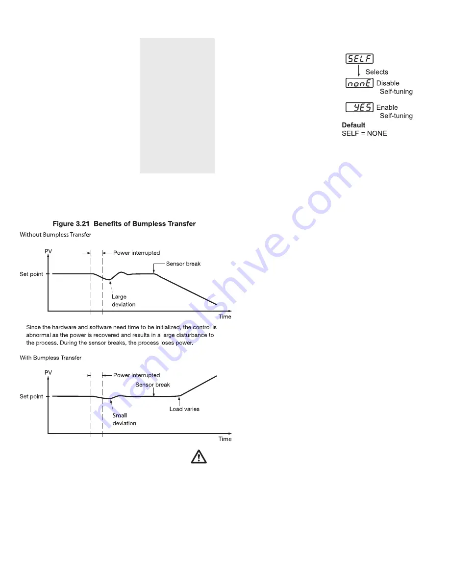
When bumpless transfer is configured, the correct con-
trol variable is applied immediately as power is recov-
ered, and the disturbance is small. During sensor
breaks, the controller continues to control by using its
previous value. If the load doesn’t change, the process
will remain stable. If the load changes, the process may
run away. Therefore, you should not rely on bumpless
transfer for extended periods of time. For fail safe rea-
sons, an additional alarm should be used to announce to
the operator when the system fails. For example, a sen-
sor break alarm, if configured, will switch to failure state and tell
the operator to use manual control or take proper security action
when the system enters failure mode.
3–18 Self tuning
Self-tuning, which was designed
using an innovative algorithm, pro-
vides an alternate option for tuning
the controller. It is activated when
YES is selected for SELF. When self-
tuning is working, the controller will
change its working PID values and
compare the process behavior to pre-
vious cycles. If the new PID values
achieve better control, then it
changes the next PID values in the
same direction. Otherwise, it changes
the next PID values in the reverse
direction. When an optimal condition is obtained, the optimal
PID values will be stored in PB1, TI1, and TD1, or PB2, TI2, and
TD2, as determined by the event input conditions. See section 4-
1. When self-tuning is completed, the value of SELF will change
from YES to NONE to disable the self-tuning function.
When self-tuning is enabled, the control variables are tuned
slowly so that the disturbance to the process is less than auto-tun-
ing. Usually, self-tuning will perform successfully with no need
to apply additional auto-tuning.
Exceptions:
Self-tuning will be disabled as soon as one
of the following conditions occurs:
1. NONE is selected for SELF.
2. The controller is used for on-off control, that is
PB=0.
3. The controller is used for manual reset, that is TI=0.
4. The controller is in a loop break condition.
5. The controller is in failure mode (e.g., sensor break).
6. The controller is in manual control mode.
7. The controller is in sleep mode.
8. The controller is being calibrated.
If self-tuning is enabled, auto-tuning can still be used
any time. Self-tuning will use the auto-tuning results
for its initial values.
Benefits of self-tuning:
1. Unlike auto-tuning, self-tuning will produce less dis-
turbance to the process.
2. Unlike auto-tuning, self-tuning doesn’t change the
control mode during the tuning period. It always per-
forms PID control.
3. Changing the set point during self-tuning is allow-
able. Therefore, self-tuning can be used for ramping
set point control as well as remote set point control
where the set point is changed from time to time.
Operation:
The parameter SELF is contained in the setup
menu. Refer to section 1-5 to find SELF for initi-
ating self-tuning.
Bumpless transfer
setup:
1. O1FT = BPLS
2. O2FT = BPLS
Bumpless transfer
occurs as:
1. Power starts (within
2.5 seconds)
2. Failure mode is acti-
vated
3. Manual mode is acti-
vated
4. Calibration mode is
activated
or
Self-tune Menu
Warning:
After the
system fails,
never depend on
bumpless transfer
for a long time, or
it might cause the
system to run
away.
Содержание TEC-9300
Страница 2: ...NOTES...
Страница 4: ...NOTES...
Страница 9: ...5 1 4 Keys and Displays continued...
Страница 10: ...6 1 5 Menu Overview...
Страница 12: ...8 1 7 Parameter Description NOTE For RS 232 Short J1 Open Cut J2 Using RS 232 will disable Event Input Function...
Страница 13: ...9 NOTE Parameter 1N1 continued on next page...
Страница 14: ...10 NOTE Parameter O1TY continued on next page...
Страница 15: ...11...
Страница 16: ...12...
Страница 17: ...13 Note Calibration menu is for supplier configuration use only...
Страница 18: ...14...
Страница 24: ...20 2 11 Output 1 Wiring...
Страница 25: ...21 2 12 Output 2 Wiring...
Страница 27: ...23 2 15 RS 485...
Страница 62: ...58...
Страница 63: ...59...
Страница 64: ...60 NOTES...
Страница 69: ...65 9 3 Parameter Table...
Страница 70: ...66...
Страница 71: ...67...
Страница 72: ...68...
Страница 73: ...69...
Страница 74: ...70...
Страница 75: ...71...
Страница 76: ...72...
Страница 77: ...73...
Страница 78: ...74...
Страница 79: ...75...
Страница 80: ...76 P 100 0 RC16 07 Lo 9 3 Communication Examples...
Страница 81: ...77 A 1 Menu Existence Conditions...
Страница 82: ...78...
Страница 83: ...79...
Страница 84: ...80 A 2 Factory Menu Description...
Страница 89: ...85 A 4 Memohe following table as a master copy for your settings...
Страница 90: ...86...


