Page 10 of 16
3–5 Configuring User Menu
Most conventional controllers are designed with a fixed order in
which the parameters scroll. The x100 series have the flexibility
to allow you to select those parameters which are most significant
to you and put these parameters at the front of the display se-
quence.
SEL1~SEL8:
Selects the parameter for view and change in the
user menu.
Range: LOCK, INPT, UNIT, DP, SHIF, PB, TI, TD, O1HY,
CYC1, OFST, RR, O2HY, CYC2, CPB, DB, ADDR, ALHY
When using the up and down keys to select the parameters, you
may not see all of the above parameters. The number of visible pa-
rameters is dependent on the setup condition. The hidden param-
eters for the specific application are also blocked from the SEL
selection.
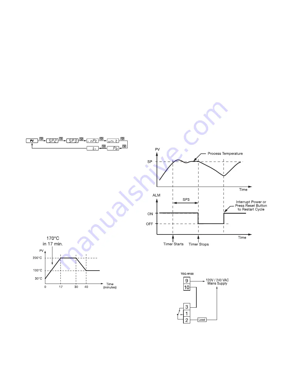
Example:
OUT2 set for DE.LO PB= 100.0 SEL1 set for INPT
SEL2 set for UNIT SEL3 set for PB SEL4 set for TI
SEL5~SEL8 set for NONE
Now, the upper display scrolling becomes:
3–6 Ramp
Ramp
The ramping function is performed during power up as well as any
time the set point is changed. If MINR or HRR is chosen for
RAMP, the unit will perform the ramping function. The ramp rate
is programmed by adjusting RR. The ramping function is disabled
as soon as failure mode, manual control mode, auto-tuning mode
or calibration mode is entered.
Example without dwell timer
Select MINR for RAMP, select °C for UNIT, select 1-DP for DP,
set RR=10.0. SV is set to 200°C initially, and changed to 100°C
30 minutes after power-up. The starting temperature is 30°C. After
power-up, the process runs like the curve shown below:
Note:
When the ramp function is used, the lower display will show
the current ramping value. The ramping value is an artificially de-
termined setpoint created and updated by the control to match the
ramp rate set by the user. However, it will revert to show the set
point value as soon as the up or down key is touched for adjust-
ment. The ramping value is initiated to process value either on
power-up or when RR and/or the set point are changed. Setting
RR to zero means no ramp function.
3–7 Dwell Timer
The alarm output can be configured as a dwell timer by selecting
TIMR for ALFN (alarm function). As the dwell timer is config-
ured, the parameter SP3 is used for dwell time adjustment. The
dwell time is measured in minutes ranging from 0.1 to 4553 min-
utes. Once the process reaches the set point the dwell timer starts
to count down to zero (time out). The timer relay will remain un-
changed until time out. For the dwell timer to control the heater,
the heater circuit (or contactor) must be wired in series with the
alarm relay. Note the following diagram located below and also
Figure 2.20.1 on page 11. When the dwell timer times out, the
heater will be turned off. The dwell timer operation is shown in
the following diagram.
After time out, the dwell timer can be restarted by pressing the
RESET key.
The timer stops counting during manual control mode, failure
mode, the calibration period and the auto-tuning period.
If the alarm is configured as a dwell timer, ALHY and ALMD are
hidden.
Dwell Timer Function Wiring Diagram
Figure 3.6 Dwell Timer Function
Figure 3.5 RAMP Function
Содержание PCM10005
Страница 3: ...Page 3 of 16 1 5 Menu Overview...
Страница 5: ...Page 5 of 16 Parameter Descriptions page 2 of 2...
Страница 6: ...Page 6 of 16 Alarm Wiring...
Страница 14: ...Page 14 of 16 Table A 1 Error Codes and Corrective Actions...


