background image


  TSA-200 / TSA-200XT / TSA-240 / TSA-240XT 

© 2010 –


2014 Telefire Fire & Gas Detectors Ltd 


Revision 1.06   July 2014 


Page 57 of 79 

16 

Control Panel Configuration and Programming 

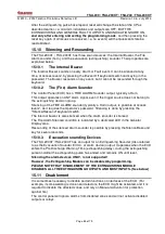
The TSA-200 product family's operating parameters can be easily configured and 
modified in the field, by programming the required parameters, to allow for the specific 
requirements of each site. 
System parameters modification is limited to access level 3, operator/programmer, 
through the front panel, or access level, using Telefire's proprietary and dedicated PC 
SW. 

16.1 

Programming by a PC 

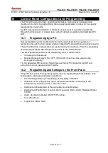
Some programming and modifications cannot be performed by the operator or 
technician, through the front panel, and are limited to PC programming at access level 4. 
These modifications of parameters are performed by connecting a PC with a proprietary 
and dedicated Telefire SW through a serial link, to the Control Panel. 
The list of parameters that can be modified by a PC is shown below: 


Changing the Passwords 


Manual Release Delay ON or OFF. (When ON it has the same value as the 
Extinguishing Delay) 

For the dedicated SW and the TSA-200 product family PC programming SW and 
instruction manual, please contact Telefire. 

16.2 

Programming and Settings by the Front Panel 

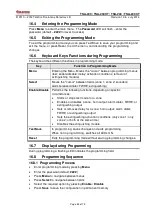
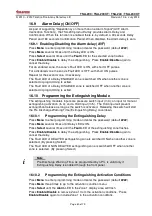
Using the front panel, the operator/programmer can modify the general settings, zone 
configuration, and output activation conditions. 


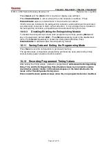
Pre Discharge Warning Time (Extinguishing Delay) ON/OFF 


Selection of the extinguishing group members (elements contributing to the 
extinguishing decision), Zone 1, Zone 2 or both 


Disablement/Enablement of the extinguishing zone (Module). 


Disablement/Enablement of zones, Alarm sounder (Horn), Alarm/Released Dialer, 
FWRE. 


Alarm Verification (Delay) ON/OFF (Per Zone). 


Test (Per Zone). 


Lights Test (LEDs Test). 


Содержание TSA-200

Страница 1: ...Alarm Control Panel Technical Manual TELEFIRE FIRE GAS DETECTORS LTD PO Box 7036 Petach Tikva 49250 Israel Tel 972 3 970 0400 Fax 972 3 921 1816 eMail info telefire co il Web www telefire co il TSA TS...

Страница 2: ...granted nor liability assumed in relation thereto unless specifically undertaken in TELEFIRE FIRE AND GAS DETECTORS sales contract or order confirmation Information contained herein is periodically up...

Страница 3: ...Limiting the consequences of faults and Suitability for use in various environment to Important Notes Move TSA 200 TSA 200XT Control Panel Assembly Before Installation Add header Wiring Consideration...

Страница 4: ...s are used interchangeably throughout this manual i Note The terms Trouble as used in NFPA 72 guideline and UL 864 standard and Fault as used in EN 54 standards are used interchangeably throughout thi...

Страница 5: ...ON 4 3 6 NUMBER OF DETECTORS 4 3 7 TSA 200 TSA 200XT EN CERTIFICATION 4 3 8 UL 864 COMPATIBILITY 4 3 9 SUITABILITY OF USE IN VARIOUS ENVIRONMENTS 5 3 10 LIMITING THE CONSEQUENCES OF FAULTS 5 4 TERMS D...

Страница 6: ...D TEST 33 10 3 OUTPUTS TEST 33 10 4 ARMING THE EXTINGUISHING DEVICE 33 10 5 CHANGE PASSWORD 33 10 6 SYSTEM ADDITIONAL DOCUMENTATION 33 10 7 CONNECTING A TDM 500I DIALER 34 11 EXTINGUISHING 35 11 1 ADD...

Страница 7: ...NG THE QUIESCENT CONDITION AFTER EXTINGUISHING 51 14 8 FAULT STATE 51 14 9 DISABLEMENT STATE 51 14 10 TEST STATE 52 15 OPERATING INSTRUCTIONS 53 15 1 DEFAULT OPERATION 53 15 2 MANUAL ONLY 53 15 3 MANU...

Страница 8: ...T 68 22 STANDARDS COMPLIANCE AND APPROVALS 69 22 1 CE LABEL 69 Table of Figures Figure 1 TSA 200 TSA 200XT System Symbolic Functional Diagram 8 Figure 2 Module location 21 Figure 3 Chassis Mounting Ho...

Страница 9: ...Figure 22 Keyboard 46 Figure 23 Extinguishing Display Area 47 Figure 24 TSA 200 TSA 200XT Programming Menu Structure Access Level 3 58 Figure 25 TSA 240 TSA 240XT Programming Menu Structure Access Lev...

Страница 10: ...tion for detectors dependant on using Telefire detectors a function that required until now analog addressable panels Walk test mode allows for detector testing by only one technician whilst discrimin...

Страница 11: ...ith requirements Output to fault warning routing Equipment EN 54 2 Section 8 9 option with requirements Test condition EN 54 2 Section 10 option with requirements 2 2 UL 864 The TSA 200 TSA 200XT TSA...

Страница 12: ...o Zones Coincidence Two zones coincidence a mandatory requirement in some European countries is explained below When the ECD is configured for two zones coincidence a trigger from one of the zones whi...

Страница 13: ...re type A or type B depending on the configuration of the TSA 200 TSA 200XT TSA 240 TSA 240XT 3 5 Note Regarding Default Configuration i Note By default the TSA 200XT and TSA 240XT are programmed for...

Страница 14: ...rect sunlight or near sources of heat It is recommended to install the CP in an electrically quiet location i e away from high power cables motors etc 3 10 Limiting the Consequences of Faults See Powe...

Страница 15: ...SA 240XT 2010 2014 Telefire Fire Gas Detectors Ltd Revision 1 06 July 2014 Page 6 of 53 i Note Relays contacts are neither monitored nor current limited Use external protective circuitry to protect th...

Страница 16: ...wer Supply Equipment PW Password M Minute Number FACP Fire Alarm Control Panel FDAS Fire Detection and Fire Alarm System FWRE Fault Warning Routing Equipment Fault Dialer FARE Fire Alarm Routing Equip...

Страница 17: ...rawing Figure 1 TSA 200 TSA 200XT System Symbolic Functional Diagram The TSA 200 TSA 240 is Fire Alarm Control Panel FACP also termed a Control and Indication Equipment CIE It relates to the left side...

Страница 18: ...egulations and the specific instructions by the manufacturer i Note All maintenance work should only be performed by trained qualified and certified personnel Personnel that work on this equipment mus...

Страница 19: ...ry wires are disconnected from the battery Remove batteries after assembling protective terminals covers from the CP before moving or shifting the Control Panel Keep the area near the batteries termin...

Страница 20: ...cess to level 1 and 2 functions and allows access to additional functions such as programming and access for functions performed during installation i Note Access levels 2 and 3 have different passwor...

Страница 21: ...2 is the Alarm Dialer output Output 3 is the FWRE Fault Dialer output but is not referred to by a number only by name Open Collector outputs The MB has two Open Collector outputs named OC Open Collec...

Страница 22: ...k5 Non condensing IP rating 30 POWER RATINGS Mains Supply 85 264Vac 47 63Hz From Data Sheet Mains Supply Current Typical 0 75A 115Vac 0 5 A 230Vac From Data Sheet Mains Supply Fuse Not Applicable No u...

Страница 23: ...00XT TSA 240 TSA 240XT 110mA two zones in alarm CP Only extinguisher OFF Current consumption TSA 200XT TSA 240 TSA 240XT 160mA two zones in alarm CP Only extinguisher ON Max Current from Batteries 3A...

Страница 24: ...ched DC FWRE output Level Activation 24V DC 0 1A 3rd out referred to by name only Power Off when activated MB OPEN COLLECTOR OUTPUTS OC outputs are not monitored OC1 24V Nominal 50mA Zone 1 OC 2 24V N...

Страница 25: ...inputs characteristics Input 4 Manual Activation See above for inputs characteristics Input 5 Hold Abort See above for inputs characteristics Inhibit PC Programmable EM1 Extinguishing Module outputs E...

Страница 26: ...detailed explanation GENERAL Input nominal quiescent voltage current 23 0V 5 0mA Current Limit Terminal block wire capacity 12 18 AWG Max number of detectors per zone 32 Number of detection zones 2 To...

Страница 27: ...TSA 200 TSA 200XT TSA 240 TSA 240XT 2010 2014 Telefire Fire Gas Detectors Ltd Revision 1 06 July 2014 Page 18 of 53 i Note Specifications are subject to change without prior notice...

Страница 28: ...and the maximum current drawn from of each single output is below its allowed limit you can add devices such as multiple sounders strobes etc provided that each single output limit is not violated and...

Страница 29: ...anel EM1 Outputs Output 3 Extinguisher not silenceable Output 4 Extinguishing EVAC Strb Sounder not silenceable Timing parameters Extinguishing Delay 0 seconds No Delay Extinguisher Pulse Duration 20...

Страница 30: ...s as the front panel which is comprised of a display keyboard unit serving as the User Interface The TSA 200 product family has an internal COTS Power Supply Charger located at the top left corner of...

Страница 31: ...he max allowed current draw from the batteries occurs when the mains are disconnected or are OFF is 3A limited by a PTC element Type and rating of batteries The ECD requires two 12V 5AH sealed Lead Ac...

Страница 32: ...9 840 ft 12 AWG 3 31 mm 4 800 m 15 750 ft Table 2 IDC cable selection 9 1 4 Cabling Planning Output Lines and 24Vdc Out Use a 2 wire cable 12 18 AWG 0 8 to 3 3 mm2 for Output Lines and 24Vdc Out conn...

Страница 33: ...supervise and clearly see the display and indicators The back of the box has several dimples In three of these dimples there are mounting holes Two holes close to the top of the box and one mounting h...

Страница 34: ...they must be plugged with an appropriate secure cover plug to maintain the required protection level 9 3 2 Wiring Considerations The TSA 200 product family is supplied in working condition fully assem...

Страница 35: ...ent from a 24 Vdc source use appropriately sized cables Wire specifications should be between 12 and 18 AWG and the cable resistance running between the 24 Vdc source to the I O module and from the I...

Страница 36: ...PUT LINES USED OR UNUSED MUST BE TERMINATED PROPERLY i Note DO NOT CONNECT EOL RESISTORS TO RELAYS OUTPUTS AND 24V OUTPUTS i Note Most extinguishing adapters have on board EOL resistors so no addition...

Страница 37: ...inside of the ECD s door i Note Always fill and update the Extinguishing Delay and Extinguishing duration in the allocated space of the label i Note In the following drawings and in the TSA 200 produ...

Страница 38: ...ctors Ltd Revision 1 06 July 2014 Page 29 of 79 Figure 5 TSA 200 TSA 200XT Connectors Label Figure 6 TSA 240 TSA 240XT Connectors Label Connect the inputs 24 volt output and control panel outputs dial...

Страница 39: ...e detectors and Manual Call Points MCP are shown Also shown is a Fire Alarm Device alarm sounder typically a horn battery input lines and other lines are omitted for clarity 9 8 Connecting the Mains P...

Страница 40: ...OUND WIRE OF THE AC INPUT CABLE Yellow Green wire and the short Yellow Green PS ground wire DIRECTLY THE PANEL S CHASSIS GROUND SCREW USING SERRATED WASHERS AS SHOWN Figure 8 Connecting the grounding...

Страница 41: ...d the long black wire to the free NEGATIVE terminal of the battery and the bat terminal block on the MB Observe Batteries polarity Wrong connection can cause damage to the ECD Assemble the protective...

Страница 42: ...stem to ensure that they are activated properly 10 4 Arming the Extinguishing device Arm the extinguishing devices i Note The Control and Indicating Equipment CIE is now fully functional and with the...

Страница 43: ...n 2 01 08 or higher see label on TDM 500i Press Prog the display shall show _ enter the password default 2222 The display shall show P Press 1 The display shall show d Press Display Configuration Rang...

Страница 44: ...e EM Presence and adapts to it Note The EM1 and the EM1 Rev 1 1 have the same terminal block connection The differences are INTERNAL ONLY 11 2 A Typical Application Fire Extinguishing The following ex...

Страница 45: ...single TLA 130 adaptor connected to the extinguishing output FIKE GCA gas cylinders A single TLA 22 adaptor connected to the extinguishing output FirePro aerosol generators A single TLA 44 1 or TLA 44...

Страница 46: ...igure 11 Connecting a SAFE solenoid operated gas cylinder 11 6 Gas Extinguishing FIKE Solenoid Operated Gas FIRERASER Cylinders The TSA 200XT TSA 240XT can activate a FIKE solenoid operated gas FIRERA...

Страница 47: ...cylinder 11 8 Aerosol Extinguishing FirePro Aerosol Generators The TSA 200XT TSA 240XT can activate a FirePro aerosol generator via a TLA 44 extinguishing adapter It is possible to connect up to four...

Страница 48: ...ices connected to the TLA 44 The module s output lines to the aerosol devices are supervised for open circuit Figure 14 Connecting a FirePro Aerosol Generator 11 9 Aerosol Extinguishing GreenEX Aeroso...

Страница 49: ...ct family to s supervising control panel It is possible to connect the TRA 1 adapter module to the TSA 200 product family Alarm and Fault relays to a zone in a conventional control panel or an input m...

Страница 50: ...Panel Display and keyboard The display is made up of a 27 single LEDs Three columns of 9 LEDs each each indicating a condition status or event The keyboard has 8 keys i Note The 5 Left bottom LEDs ar...

Страница 51: ...explained in the text below If a 12094 certified CIE CDE Extinguishing Control Panel is required please consult Telefire LTD about the TSA 200X and other products With the TSA 200 some events cause t...

Страница 52: ...Alarm Sounder s Horn are activated Off when not activated or silenced Test Yellow LED ON when the CP is in the Test mode Power Green LED Indicates the presence of the two input power sources AC mains...

Страница 53: ...zzer Off and entering the operator s password switches the LED and the general fault LED ON steadily and silences the buzzer Auxiliary 24V Yellow LED Flashes to indicate an Auxiliary 24V or Auxiliary...

Страница 54: ...s Color and Function Alarm Red LED Flashes to indicate an Alarm in that zone The general Alarm LED flashes also Pressing Ack Buzzer Off and entering the operator s password switches the LED and the ge...

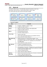
Страница 55: ...e Used for Lamp Test Used to save programming options in permanent memory Used to enter the numeric value 4 Manual Exting Only Allows the selection of extinguishing activation mode automatic manual or...

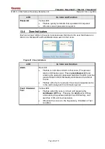
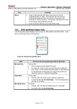
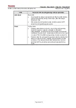
Страница 56: ...splay area is active for TSA 200XT and TSA 240XT a fire Alarm and extinguishing control panels Figure 23 Extinguishing Display Area LED Its Color and meaning during normal operation Manual Only Yellow...

Страница 57: ...F when the extinguishing pulse ends Fault Yellow LED Flashes when there is a fault in any of the extinguishing module s inputs or outputs changes to ON when acknowledged and stays ON until the faults...

Страница 58: ...ol and Indicating Equipment CIE will enter alarm state when receiving an alarm from the same or from the other zone During alarm confirmation time the Control and Indicating Equipment CIE will enter a...

Страница 59: ...ro the CP enters the Activated Releasing state triggers the extinguisher immediately skipping the Pre Discharge Warning Time During the Pre Discharge warning time or Countdown the Delay LED flashes th...

Страница 60: ...has to be performed again If all issues are resolved and there are no pending events after entering and exiting the programming mode the ECD returns to the quiescent state See Operating Instructions b...

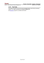
Страница 61: ...Detectors Ltd Revision 1 06 July 2014 Page 52 of 79 14 10 Test State Test states allow testing the Control and Indicating Equipment CIE without activating outputs This state is indicated by the Test a...

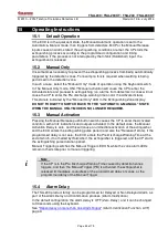
Страница 62: ...T TO SWITCH BACK TO THE AUTOMATIC MANUAL STATE WHEN THE MANUAL ONLY MODE IS NO LONGER REQUIRED 15 3 Manual Activation Pressing the Manual Release push button switch causes the CP to enter the Activate...

Страница 63: ...e extinguishing delay elapses when they are switched OFF the Extinguishing Strobe Sounder is switched OFF and the Fault state is entered The General Fault LED Relay and Dialer flash and the buzzer sou...

Страница 64: ...e FIRE ALARM sounder typically a Horn output is possible at access level 2 as it requires the Operator s password Silencing is done by pressing the Silence Resound keyboard switch The internal buzzer...

Страница 65: ...o the TB of the specific port also flashes Also the specific fault LED in the front panel general area middle or left column is ON The buzzer sounds the Fault signal 1 4 ON OFF time ratio Fix faults w...

Страница 66: ...connecting a PC with a proprietary and dedicated Telefire SW through a serial link to the Control Panel The list of parameters that can be modified by a PC is shown below Changing the Passwords Manual...

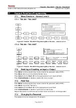
Страница 67: ...ors Ltd Revision 1 06 July 2014 Page 58 of 79 16 3 Menu Structure Access Level 3 16 3 1 TSA 200 TSA 200XT Figure 24 TSA 200 TSA 200XT Programming Menu Structure Access Level 3 16 3 2 TSA 240 TSA 240XT...

Страница 68: ...ialer FWRE extinguishing Enable Disable Performs the following functions depending on specific circumstances Starts or stops test mode for a zone Enables or disables a zone horn output alarm dialer FW...

Страница 69: ...g Module The extinguishing module s inputs are pressure switch input In 3 an input for manual extinguishing activation In 4 and a Hold input In 5 The Hold input will prevent extinguishant release as l...

Страница 70: ...programming mode by pressing Menu and key in the password default 2222 Press Menu repeatedly to get to the disablement menu Press Select repeatedly to access the Extinguishing Module Press Enable Dis...

Страница 71: ...amming mode and enter the password default 1111 Press Menu twice to go to the Enable Disable menu Press Select until the Fault LED for the appropriate zone or output will flash Press Enable Disable to...

Страница 72: ...0 2014 Telefire Fire Gas Detectors Ltd Revision 1 06 July 2014 Page 63 of 79 17 5 Lamp Test Lamp test will activate all LEDs in the control panel and the internal buzzer for two seconds for testing pu...

Страница 73: ...ve the dummy load and connect the extinguisher to the extinguishing output or output lines Connect mains and batteries Fix all problems Verify that the ECD is in the quiescent state i Note Do not acce...

Страница 74: ...Gas Detectors Ltd Revision 1 06 July 2014 Page 65 of 79 If the document is not attached to the CP front panel a note at the bottom stating that it shall be framed and placed near the CP for ready ref...

Страница 75: ...00 product family clean and dry If necessary clean the outside of the enclosure with a slightly damp cloth The batteries should be tested and replaced according to the instructions of the battery s ma...

Страница 76: ...erform a Field Test of each zone Maintenance and test actions shall be conducted by a company or service technician authorized by Telefire Records of all inspection and maintenance activities should b...

Страница 77: ...sher Extinguishing Sounder Pressure Switch Manual Release and Hold Troubleshooting and fault analysis can be performed by observing the display analyzing the source of the fault by monitoring the Fron...

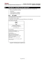
Страница 78: ...200 product family have the following certification and approvals EN 54 2 and EN 54 4 certified CE Marked UL 864 edition 9 compatible GOST 53325 2009 certified 22 1 CE Label The TSA 200 200XT is CE ma...

Страница 79: ...h the extinguishant restore extinguishing capability and return to normal operation Fault Condition Action Silencing The General and specific Fault LEDs turns on and the internal buzzer sounds Take ap...

Отзывы: