


TSA-200 / TSA-200XT / TSA-240 / TSA-240XT
© 2010 –
2014 Telefire Fire & Gas Detectors Ltd
Revision 1.06 July 2014
Page 23 of 79
9
Installation
9.1
System Installation Planning
9.1.1 Capability Planning
Verify that the total number of input initiating devices does not exceed local regulations
of the number of initiating devices per zone, area or other limitations. Verify that the
number of zones satisfies all the relevant requirements.
9.1.2 Calculating Current Requirement and Battery Capacity
For every control panel, calculate the total current consumption of all devices such as
sounder, beacons, extinguishing cylinders actuators, Extinguishing Activated sign,
automatic dialer etc... Ensure that the total current draw does not exceed 1.5A.
The batteries are rechargeable, sealed lead acid batteries, in total voltage of (Nominal)
24 volts (two 12 volt batteries in series) and capacity of 5 AH.
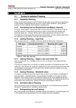
9.1.3 Cabling Planning – Input lines
Use a 2-wire cable, 12 – 18 AWG (0.8 to 3.3 mm2) for IDC (zone) connections.
Wire Type
Cross-Section (mm
2
)
Maximum IDC Length
18 AWG
0.82 mm 1,200 m
3,940 ft
16 AWG
1.31 mm 1,900 m
6,230 ft
14 AWG
2.08 mm 3,000 m
9,840 ft
12 AWG
3.31 mm 4,800 m
15,750 ft
Table 2
IDC cable selection
9.1.4 Cabling Planning – Output Lines and 24Vdc Out
Use a 2-wire cable, 12 – 18 AWG (0.8 to 3.3 mm
2
) for Output Lines and 24Vdc Out
connections.
The length of output lines and 24Vdc out cabling depends on the required current and
cable size. Ensure that the maximum voltage drop to the end of the line at full load does
not exceed 3V and will leave the last device the minimal operating voltage as per the
manufacturer's specification.
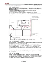
9.1.5 Cabling Planning – Shielded Cables
It is highly recommended to avoid outdoor wiring due to the increased susceptibility to
lightning strikes. Overhead cables running between buildings or on roofs should be
shielded. The shield should be connected to the ground by using the Master Ground
Terminal in the control panel using the appropriate hardware. Grounding should not be
connected to any other points. Ensure continuous grounding by soldering.
9.1.6 Activation Matrix Planning
Plan the activation logic according to the requirements in accordance with the relevant
standards, regulations and mandatory requirements.
9.1.7 Extinguishing Device Planning
Size and quantity of extinguishing cylinders shall be calculated by authorized personnel
in accordance to the requirements of the consultant and local regulations.


